Ophthalmologic image processing apparatus

a technology of image processing and ophthalmology, applied in the field of ophthalmologic image processing apparatus, can solve problems such as defects, and achieve the effect of less discomfor

Inactive Publication Date: 2008-06-17
CANON KK
View PDF2 Cites 0 Cited by
  • Summary
  • Abstract
  • Description
  • Claims
  • Application Information

AI Technical Summary

Benefits of technology

[0013]The present invention has been made in view of the above-mentioned problems. Therefore, an object of the present invention is to provide an ophthalmologic image processing apparatus that produces a synthesized image with less sense of discomfort in synthesizing process for synthesizing a fundus image with an aperture mask image.

Problems solved by technology

As described above, there is the case where defects are caused in synthesizing an aperture mask with a fundus image in the conventional ophthalmologic image processing apparatus.

Method used


Image

  • Ophthalmologic image processing apparatus
  • Ophthalmologic image processing apparatus
  • Ophthalmologic image processing apparatus

Examples


Embodiment Construction

[0031]The present invention will be described in detail with reference to an embodiment shown in FIGS. 1 to 7.

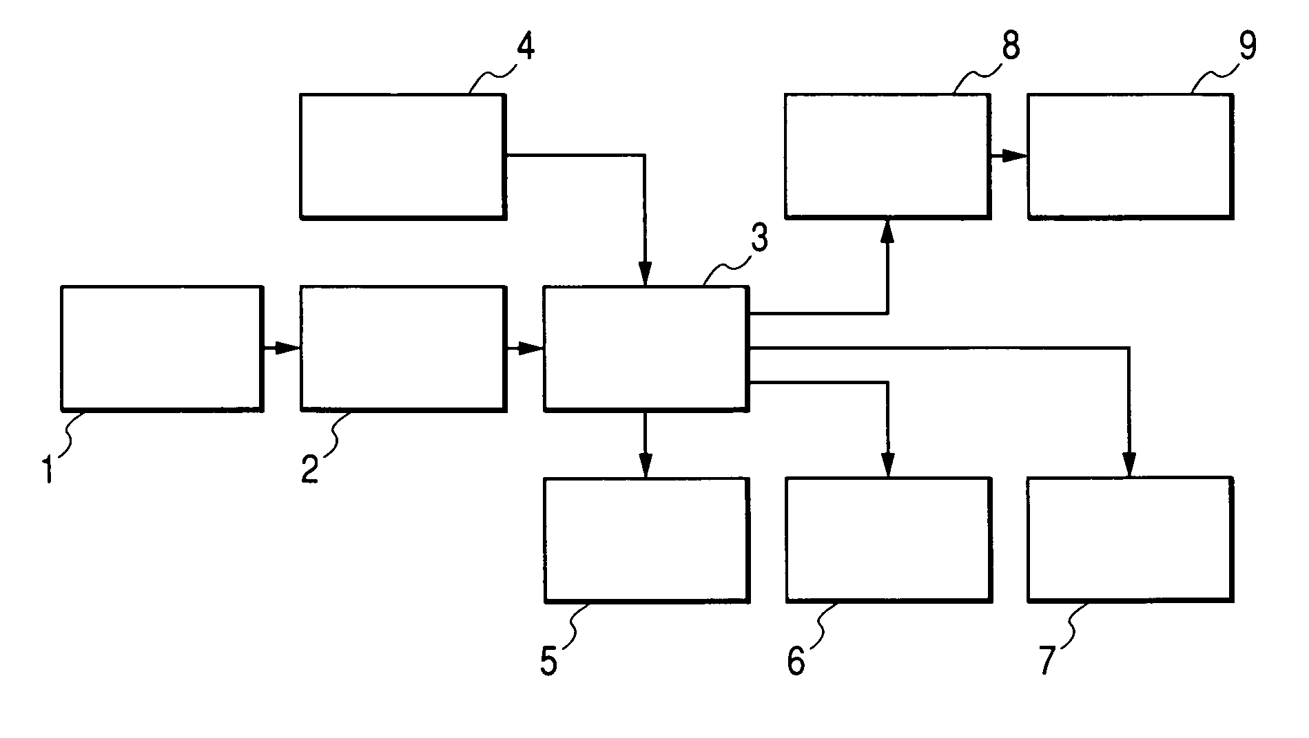
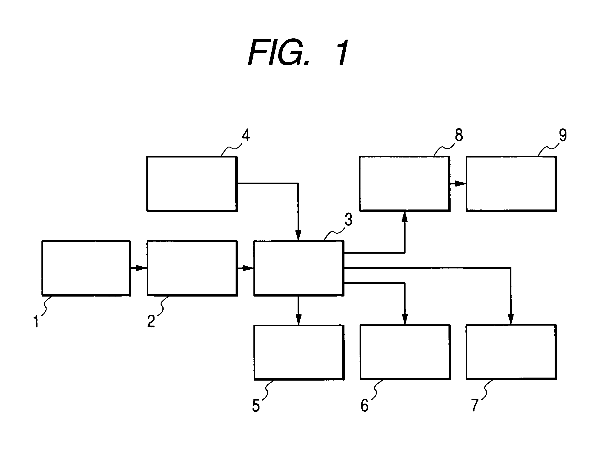
[0032]FIG. 1 is a block circuit structural diagram showing a fundus image processing apparatus according to an embodiment of the present invention. A fundus camera unit 1 is composed of a device that projects image taking light to a fundus and forms a reflection image with the light reflected from the fundus onto an image pickup device. The fundus camera unit 1 is a unit which includes an optical system, a mechanism, and an electrical unit, which are known, and takes an image of the fundus of a person to be examined to generate fundus image data. An output of the fundus camera unit 1 is inputted to an image processing apparatus 3 through an input interface 2 that inputs the fundus image data. An aperture mask input unit 4 that inputs an aperture mask image is connected with the image processing-apparatus 3.

[0033]An output of the image processing apparatus 3 is connected with...


PUM


Abstract

To synthesize an aperture mask having unnoticeable steps with a taken fundus image. In an image processing apparatus, taken fundus image data is inputted and then analyzed. After that, an aperture mask is selected and inputted as aperture mask data, and an image size of the fundus image compared with an image size of the aperture mask. The image size of the aperture mask is adjusted to the image size of the fundus image and then the fundus image data and the aperture mask data are developed in raster format to image memories. The image size of the fundus image is adjusted to the image size of the aperture mask based on the comparison result and a coefficient for low pass filtering process is determined according to the image size of the fundus image. After that, the degree of clearness of corresponding fundus image data is calculated based on each pixel value of the aperture mask data on which the low pass filtering process has been performed and the calculation result is outputted to the image memory. After the process is performed for all the pixels, a fundus area in the fundus image is moved to predetermined coordinates. A resultant fundus image is outputted as final image data to a storage device and a display memory and then a series of processes are completed.

Description

BACKGROUND OF THE INVENTION[0001]1. Field of the Invention[0002]The present invention relates to an ophthalmologic image processing apparatus used for ophthalmologic examination in an ophthalmologic clinic and the like.[0003]2. Related Background Art[0004]In a conventional fundus camera, image taking is performed with an aperture mask that performs light shielding on an area other than a central region inside a flare region located at a position immediately before an image pickup plane or at an equivalent position on an optical path, in order to determine an effective image taking area by eliminating a flare caused near a formed image, to determine a positional relationship between the image and an eye to be examined, or to determine a left or right eye in a case of picking up a pair of a papillary area and a macular area. In such fundus camera, because the aperture mask is located near an imaging plane of a fundus image, a boundary between the fundus image and the mask on the taken...

Claims


Application Information

Patent Timeline
Patent Type & Authority Patents(United States)
IPC IPC(8): A61B3/14A61B3/02A61B3/10A61B3/12
CPCA61B3/14G06T5/002G06T2207/30041
Inventor SEKIGUCHI, KIYOJI
Owner CANON KK
Why Eureka
Try Eureka