Check patentability & draft patents in minutes with Patsnap Eureka AI!

Device for protecting electric component

a technology for electric components and devices, applied in the direction of coupling device connections, machines/engines, lighting and heating apparatus, etc., can solve the problems of distorted wall surface of the cover, and achieve the effect of reducing the movement of the cover, preventing the cover from sliding, and being resistant to fractur

Active Publication Date: 2008-06-17
PANASONIC APPLIANCES REFRIGERATION DEVICES SINGAPORE
View PDF5 Cites 4 Cited by
  • Summary
  • Abstract
  • Description
  • Claims
  • Application Information

AI Technical Summary

Benefits of technology

"The present invention provides a protecting device for a compressor with a bracket and a cover. The bracket has an insert portion and a locking part with a locking hole, and the cover has a clamp and a ratchet. The insert portion has multiple projections with different lengths. The cover is securely fixed to the bracket with the ratchet as a supporting point, preventing movement. To detach the cover, only one ratchet needs to be detached, which causes only the cover to be distorted. This design is easy to attach and detach, resistant to fracture, and highly reliable."

Problems solved by technology

In order to detach the cover from the bracket, only one ratchet needs to be detached from the locking hole, which causes only the wall surface of the cover having the ratchet to be distorted.

Method used


Image

  • Device for protecting electric component
  • Device for protecting electric component
  • Device for protecting electric component

Examples


Embodiment Construction

[0022]Hereinafter, a description is made for an exemplary embodiment of the present invention, with reference to the accompanying drawings. The drawings are schematic, and thus do not indicate each positional relationship with correct dimensions. This exemplary embodiment does not limit the present invention.

Exemplary Embodiment

[0023]A description is made for an exemplary embodiment using FIGS. 1 through 6.

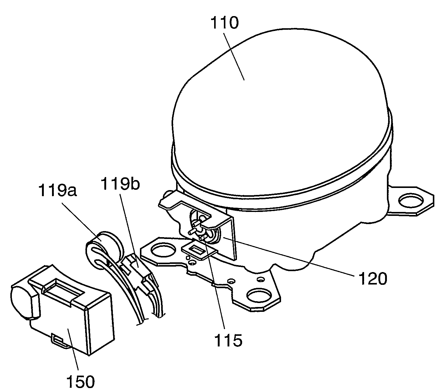
[0024]In FIGS. 1 through 6, electromotive compressor unit 110 containing its electromotive compressing element (not illustrated) is mounted thereon with glass terminal 115 for supplying the electromotive compressing element with electricity. Glass terminal 115 is connected with electric components 119a and 119b for protecting or starting the above-mentioned electromotive compressing element.

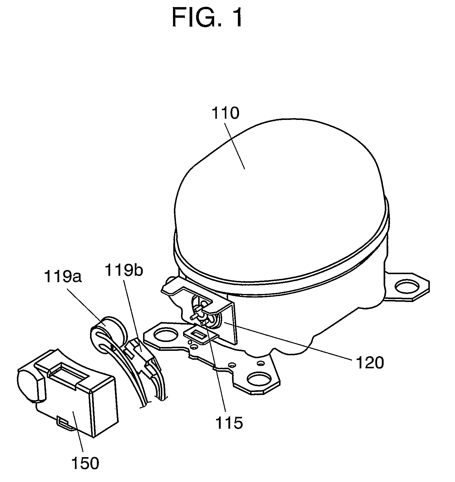
[0025]Bracket 120, made of a bend formed iron plate, such as a cold-rolled or hot-rolled steel plate, is fastened to electromotive compressor unit 110 so as to enclose glass terminal 115. Brack...


PUM


Abstract

A device for protecting an electric component for a compressor is provided, where the device is equipped with a bracket formed with an insert portion and a locking part having a locking hole, facing each other; and a cover formed with a clamp for clamping the distal end of the insert portion, and a ratchet fastened to the locking hole, and where the insert portion is formed of a plurality of projections with different length of projected portions in insert direction. This makeup enables only one ratchet to fix the cover securely to the bracket, as well as makes the cover to be resistant to fracture owing to a small distortion of the cover when detaching.

Description

[0001]THIS APPLICATION IS A U.S. NATIONAL PHASE APPLICATION OF PCT INTERNATIONAL APPLICATION PCT / JP2006 / 302784.TECHNICAL FIELD[0002]The present invention relates to a device for protecting an electric component in a hermetic electromotive compressor used for a fridge-freezer apparatus and the like.BACKGROUND ART[0003]Some conventional devices for protecting an electric component (referred to as “protecting device” hereinafter) with this type can be fixed with a single inserting operation. Such a protecting device is disclosed in Japanese Patent Unexamined Publication No. H02-33478.[0004]Hereinafter a description is made for the above-mentioned conventional protecting device with reference to FIGS. 7 and 8. FIG. 7 is an exploded perspective view of the above-mentioned device and FIG. 8 is an enlarged side view of the above-mentioned device in a state of being mounted.[0005]In FIGS. 7 and 8, electromotive compressor unit 10 containing its electromotive compressing element (not illustr...

Claims


Application Information

Patent Timeline
Patent Type & Authority Patents(United States)
IPC IPC(8): H01R13/52
CPCH01R13/447H01R13/5045H01R13/506H01R13/5213F25B2400/077F04C2240/803F25B31/00F25B49/005
Inventor SUGIYAMA, JUNICHI
Owner PANASONIC APPLIANCES REFRIGERATION DEVICES SINGAPORE
Features
  • R&D
  • Intellectual Property
  • Life Sciences
  • Materials
  • Tech Scout
  • Unparalleled Data Quality
  • Higher Quality Content
  • 60% Fewer Hallucinations
Learn More