Cranial flap fixation system and method

a cranial flap and fixation system technology, applied in the field of surgical fixation devices, can solve the problems of excessive force applied to the cranial flap and surrounding cranial bone, many current clamping designs are limited, and most existing clamping designs do not address the need to return to the surgical site without undue effort, etc., to achieve enhanced variability, infinite adjustability, and enhanced pressure

Inactive Publication Date: 2008-06-17
OSTEOMED
View PDF13 Cites 21 Cited by
  • Summary
  • Abstract
  • Description
  • Claims
  • Application Information

AI Technical Summary

Benefits of technology

[0005]Technical advantages of particular embodiments of the present invention include a cranial flap fixation system and method that provide enhanced variability in the amount of pressure applied to a cranial flap and adjacent cranial bone depending on how tightly the superior and inferior disks are brought together. Such variability is enhanced by providing a threaded superior disk with practically infinite adjustability as compared to a “ratchet” type system. This variability allows surgeons to select the appropriate amount of pressure to apply along a cranial flap joint without being limited by the design of the fixation device.
[0006]Another technical advantage of particular embodiments of the present invention is a disposable installation tool that may be used to install the fixation device, as well as remove the excess portion of the connecting rod that is left after installation. This dual functionality of the installation tool allows for quicker installations of the device and eliminates several time consuming steps found in typical fixation device installations.
[0007]Yet another technical advantage of particular embodiments of the present invention is a cranial flap fixation device that greatly reduces the risk of fixation device loosening over time. In accordance with a particular embodiment, this is accomplished using a downward-facing tab on the superior disk of the fixation device configured to reside in the gap between the cranial flap and the adjacent cranial bone and resist any rotation of the superior disk.

Problems solved by technology

However, many current clamping designs are limited in that they use ratcheting mechanisms which have a finite displacement and have the potential to apply excessive force to the cranial flap and surrounding cranial bone.
Furthermore, most existing clamping designs do not address the need to return to the surgical site without undue effort.
In addition, many current clamping designs require instrumentation that requires additional maintenance, cleaning, and sterilization, adding to the time hospitals must dedicate to such devices.

Method used


Image

  • Cranial flap fixation system and method
  • Cranial flap fixation system and method
  • Cranial flap fixation system and method

Examples


Embodiment Construction

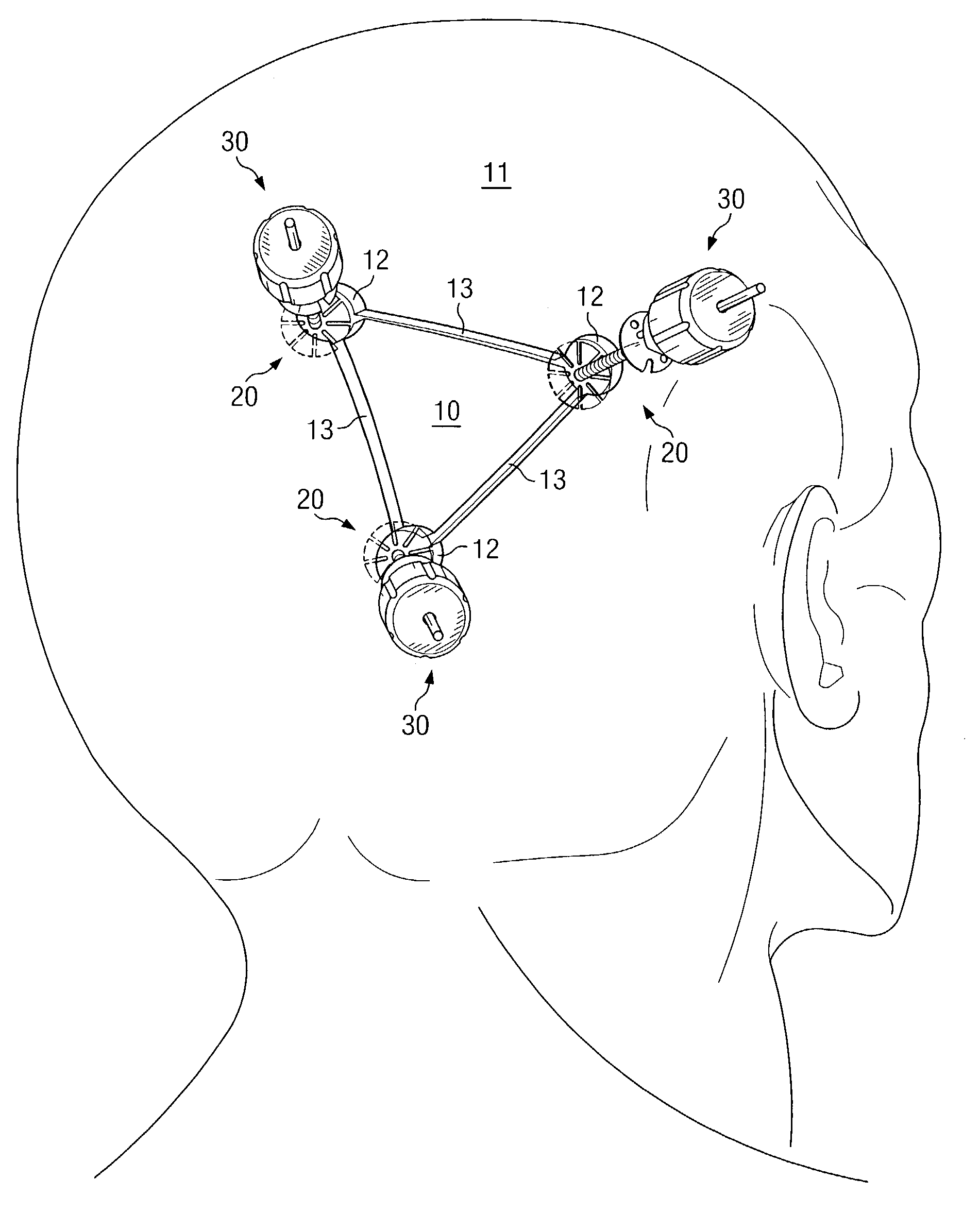
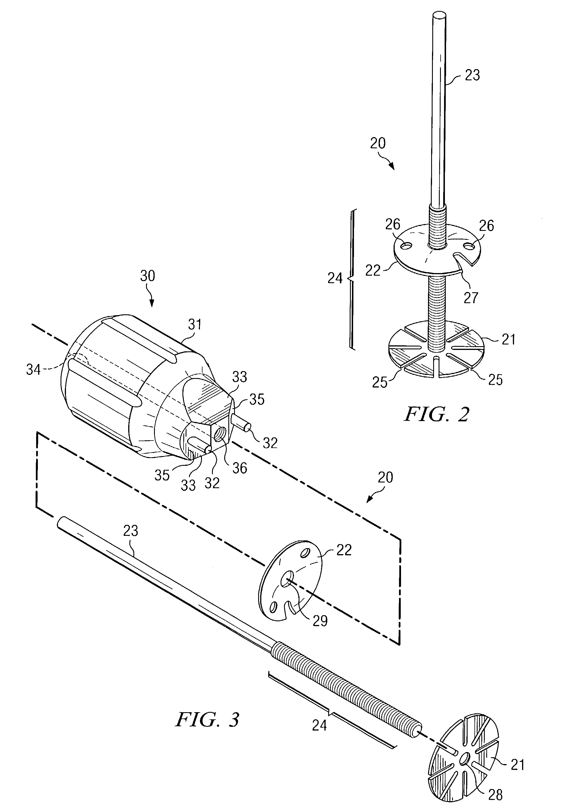
[0014]FIG. 1 illustrates a plurality of cranial flap fixation devices in accordance with a particular embodiment of the present invention. Cranial flap fixation device 20 is a fastening system used to fixate a cranial flap to the surrounding cranial bone following a craniotomy. In particular, fixation device 20 includes two circular disks that are attached via a threaded connecting rod. A cranial flap is fixated by being squeezed, along with the surrounding cranial bone, between the two disks. Due to the threaded connection between the connecting rod and the disks, fixation device offers practically infinite adjustability and, therefore, enhanced variability in the amount of pressure applied to the cranium by the two circular disks. Fixation device 20 may also be configured for use with a disposable installation tool 30, which may be used to tighten the device as well as remove the excess portion of the connecting rod left after installation.

[0015]As shown in FIG. 1, a plurality of ...


PUM


Abstract

A cranial flap fixation system and method are provided. The system includes an inferior disk coupled with a first end of a partially threaded connecting rod, and a superior disk having a central orifice operable to be threadably coupled with the connecting rod. The inferior and superior disks are configured such that upon installation, the inferior and superior disks cooperate with the connecting rod to apply pressure to a cranial flap and an adjacent cranial bone.

Description

TECHNICAL FIELD OF THE INVENTION[0001]The present invention relates in general to the field of surgical fixation devices, and, in particular, to a cranial flap fixation system and method.BACKGROUND OF THE INVENTION[0002]To gain access to the brain for neurosurgical procedures, holes are often cut in the skull. These holes are created by making one or more bur holes in the cranial bone and then cutting the bone to connect the bur holes. The segment of the cranial bone removed in this fashion is referred to as a cranial flap. Once the surgical procedure is complete, however, the cranial flap must be repositioned in the cavity created by its removal. This is done by placing the cranial flap in its original position and fastening the flap to the surrounding cranial bone.[0003]Currently a number of methods for cranial flap fixation exist. One such method utilizes clamping designs to close the cranial flap. Generally, these designs consist of two circular disks that are attached via a ste...

Claims


Application Information

Patent Timeline
Patent Type & Authority Patents(United States)
IPC IPC(8): A61B17/58A61B17/68A61B17/88
CPCA61B17/688A61B17/88A61B17/8869
Inventor AHMAD, SHAHER A.PATTERSON, CHAD JOSEPHTHORNHILL, LISA REGINA
Owner OSTEOMED
Why Eureka
Try Eureka