Method and radiation source for generating pulsed coherent radiation

Active Publication Date: 2006-11-30
MAX PLANCK GESELLSCHAFT ZUR FOERDERUNG DER WISSENSCHAFTEN EV
View PDF14 Cites 72 Cited by
  • Summary
  • Abstract
  • Description
  • Claims
  • Application Information

AI Technical Summary

Benefits of technology

[0017] A further particular advantage of the invention is given by the high variability with regard to the provision of the non-linear medium in the low pressure environment. According to a first alternative, the complete set-up comprising the resonant cavity and the non-linear medium, possibly with the beam splitting device is provided in a vacuum chamber. According to a second alternative, the non-linear medium, possibly with the bean splitting device, is contained in a separate vacuum compartment, which is arranged in the resonant cavity. The vacuum compartment includes the non-linear medium (possibly with the beam splitting device) while the remaining resonant cavity is subjected to regular atmospheric pressure. As a further alternative, the non-linear medium (possibly with the beam splitting device) and parts of the resonant cavity can be arranged in the vacuum compartment. The inventors have found that surprisingly the adjustment of the resonant cavity is not deteriorated by windows of the vacuum compartment.
[0018] According to a second aspect, the present invention is based on the general technical teaching of providing a radiation source with a resonant cavity including a non-linear medium, which is arranged in an environment of reduced pressure. Preferably, the radiation source further includes a beam splitting device, which is arranged in or at a boundary of the environment of reduced pressure as well.
[0019] If the beam splitting device based on a reflection is arranged in the beam path of the resonant cavity with a Brewster orientation for the fundamental laser pulses in the cavity, the amplification of the

Problems solved by technology

Due to the phase-coherent addition of light pulses with the simultaneous SHG or THG process, harmonic light pulses with high repetition rates (up to GHz) can be obtained, However, the conventional generation of short wavelength radiatio

Method used


Image

  • Method and radiation source for generating pulsed coherent radiation
  • Method and radiation source for generating pulsed coherent radiation
  • Method and radiation source for generating pulsed coherent radiation

Examples


Embodiment Construction

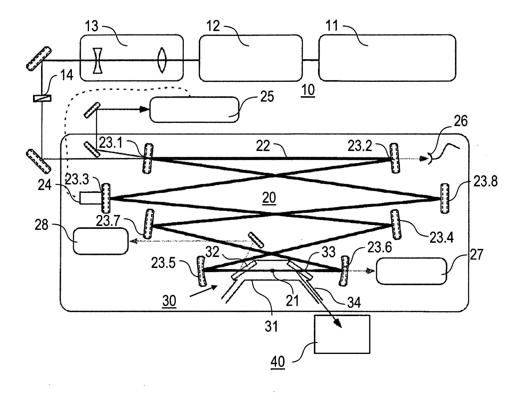
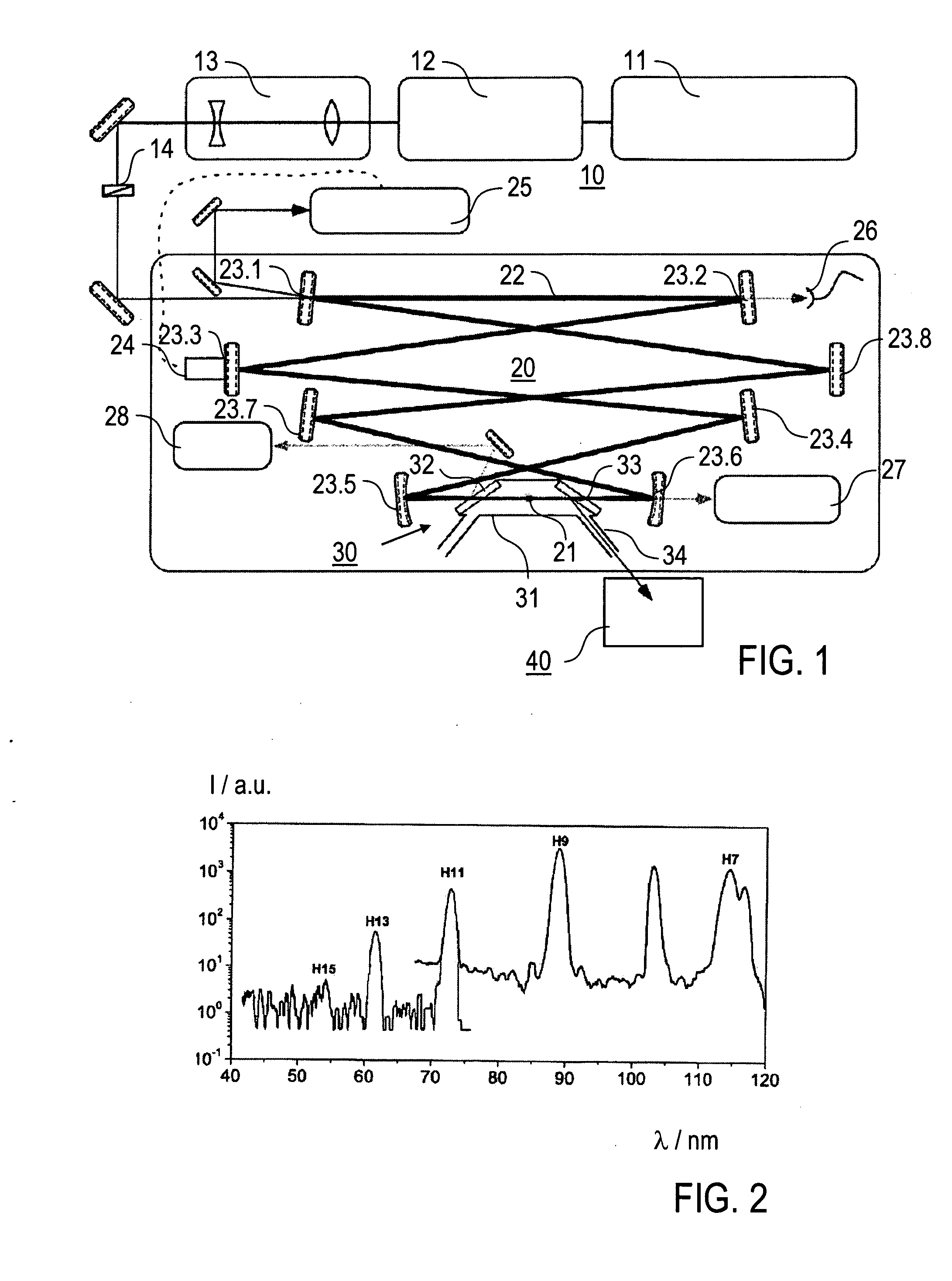
[0030] According to a first embodiment of the invention shown in FIG. 1, a radiation source 100 for generating pulsed coherent radiation comprises a laser pulse source 10, a resonant cavity 20 and an environment 30 of reduced pressure formed by a vacuum compartment 31.

[0031] The laser pulse source 10 comprises a laser oscillator 11 for generating fs laser pulses, a pulse compressor 21 (prism compressor or comparable pulse shaping optic), that compensates the dispersion of an input mirror 23.1 of the resonator cavity 20, a telescope 13, that matches the beam diameter and focus position to the modes of the resonant cavity 20, and a λ / 2 plate 14. The laser oscillator 11 is a Ti:sapphire laser (Femtolasers Femtosource 20), which delivers 20 fs pulses with 850 mW average power at a central wavelength of 800 nm and a repetition rate of 112 MHz with pulse energy of 7.7 nJ and peak power round 400 kW. The pulse compressor 21 can comprise a controllable compressor adapted for controlling th...


PUM


Abstract

A method of generating pulsed coherent radiation, comprises the step of generating high harmonic pulses by an interaction of laser light pulses with a non-linear medium contained in a resonant cavity, wherein the non-linear medium is arranged in an environment of reduced pressure. Furthermore, a radiation source of generating pulsed coherent radiation is described, comprising a laser pulse source for generating laser light pulses, a resonant cavity including a non-linear medium for generating high harmonic pulses by an interaction of the laser light pulses with the non-linear medium, wherein the non-linear medium is arranged in an environment of reduced pressure.

Description

TECHNICAL FIELD [0001] The present invention relates to a method of generating pulsed coherent radiation in the UV and XUV wavelength ranges. Furthermore, the present invention relates to a radiation source for generating pulsed coherent radiation based on a high harmonic generation (HHG). TECHNICAL BACKGROUND [0002] For the generation of X-rays, several approaches are available. The conventional X-ray generation by irradiating a target with an electron beam is typically used in medicine and material science. For microscopy and lithography applications, a laser-based radiation source has been developed, which covers the wavelength range from XUV- and UV-ranges down to X-rays (see e.g. T. Brabec et al. in “Reviews of Modern Physics”, vol. 72, 2000, p. 545). With these laser-based sources, an intense laser beam is focussed onto a target material, like e.g. a Xe jet. Due to a HHG process in the target material Xe, X-rays are emitted as described by e.g. J. Seres et al. in “Nature” (vol...

Claims


Application Information

Patent Timeline
IPC IPC(8): H01S3/10
CPCG02F2201/17G02F1/353
Inventor GOHLE, CHRISTOPHHANSCH, THEODOR W.HOLZWARTH, RONALDUDEM, THOMAS
Owner MAX PLANCK GESELLSCHAFT ZUR FOERDERUNG DER WISSENSCHAFTEN EV
Why Eureka
Try Eureka