System for plasma ignition by fast voltage rise

a plasma ignition and fast voltage technology, applied in the field of plasma processing, can solve the problems of difficult plasma ignition, complex system, non-uniform or unstable results, etc., and achieve the effects of enhancing plasma ignition, increasing the probability and variability of conditions, and increasing the likelihood of ignition

Inactive Publication Date: 2003-10-14
ADVANCED ENERGY IND INC
View PDF24 Cites 66 Cited by
  • Summary
  • Abstract
  • Description
  • Claims
  • Application Information

AI Technical Summary

Benefits of technology

Accordingly, the present invention is directed to a system for enhancing plasma ignition through manipulation of the voltage applied to the plasma electrodes in a manner which achieves advantages compared to those approaches previously used. This system is designed to achieve a manipulation so that a rapidly rising voltage waveform may act to concentrate free ions and thus increase the probability and variability of conditions which permit plasma ignition. The present invention discloses techniques which now achieve or perhaps more reliably accomplish ignition of a plasma in a thin film processing system. By making what might be seemingly subtle changes to the way in which existing equipment is operated, significant increases in the likelihood of ignition may often be achieved.
It is also an object of the present invention to permit plasma ignition at a variety of conditions especially at a lower pressure than has been heretofore possible. Similarly, it is an object of the present invention to permit more reliable plasma ignition at low operating pressures. It is thus a goal to permit more variation in the pressures possible for an plasma ignition environment and to permit ignition at pressures desired to be used in certain operating conditions.
It is a further object of the present invention to minimize or perhaps eliminate the utilization of other techniques to achieve plasma ignition. As one example, it is an object to perhaps eliminate any need for a change in pressure to effect plasma ignition. Another broad object of the present invention is to minimize the impact of ignition within a processing system. An object is thus to allow ignition while avoiding separate inputs to the processing environment.
It is another object of the present invention to avoid or minimize any requirement for additional components or systems with such a system. As one example, it is an object to eliminate any need to include sources of ions or electrons to effect plasma ignition at low pressures.

Problems solved by technology

In particular, at the lower end of the pressure range it becomes difficult to ignite the plasma, even though a plasma, once ignited, may be sustained and utilized for sputtering.
First, a pressure burst may be introduced into the system.
All of these methods add complexity to the system and may change the operating characteristics of the process so that non-uniform or unstable results may be obtained.
This dynamic environment is not only unpredictable, it may cause fluctuations in a variety of characteristics necessary to cause the gas involved to ignite into a plasma.
Thus, while in some other applications the plasma can be ignited by merely achieving the necessary conditions, in thin film processing applications, this is not always possible.
The dynamic nature of the chamber itself and its unpredictability, may make knowing the conditions necessary for ignition extremely difficult from a practical perspective.
This approach, while useful for many applications does not fully address other problematic applications.
First, as mentioned, the processing is often very delicate.
While at first glance this would appear to relate only to the operation of the plasma, not to its ignition, such is not the case as the environment during ignition itself can literally ruin the processing desired.
It may even be said that while those skilled in the art of thin film processing might typically have a great degree of skill and technical knowledge in the plasma processes themselves, those so skilled rarely combined such knowledge with equivalent understanding of process and mechanisms involved in the ignition of the plasma or the electrical circuitry characteristics as well.
The techniques used however, have not been accomplished in a manner which demonstrates the type of understanding of the environment as disclosed here.

Method used


Image

  • System for plasma ignition by fast voltage rise
  • System for plasma ignition by fast voltage rise
  • System for plasma ignition by fast voltage rise

Examples


Embodiment Construction

As can be easily understood, the basic concepts of the present invention may be embodied in a variety of ways. They involve both ignition techniques as well as devices to accomplish the appropriate technique. In addition, while some system designs are disclosed, it should be understood that these not only accomplish certain methods but also can be varied in a number of ways. Importantly, as to all of the foregoing, all of these facets should be understood to be encompassed by this disclosure. The invention broadly teaches the characteristics from which numerous techniques can be developed.

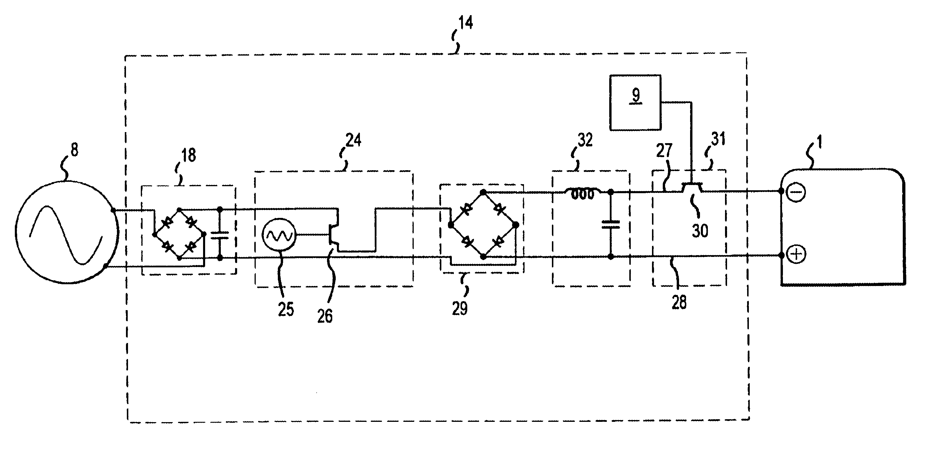
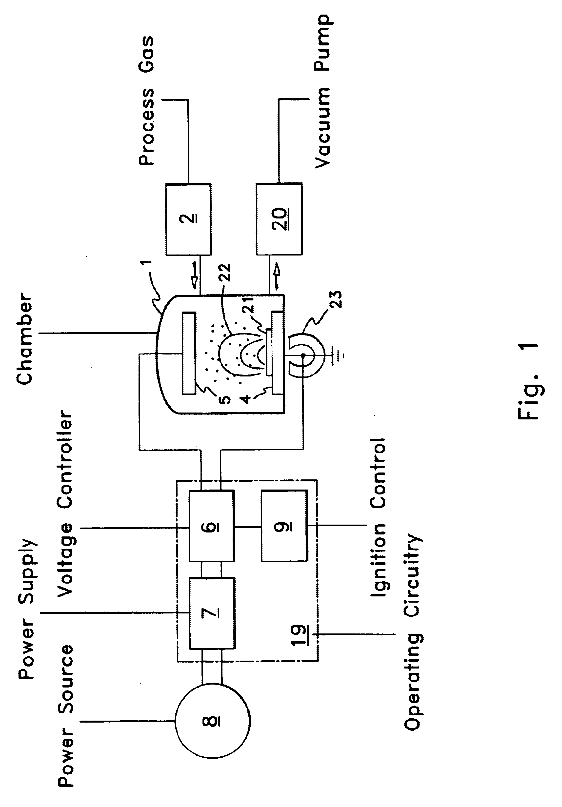
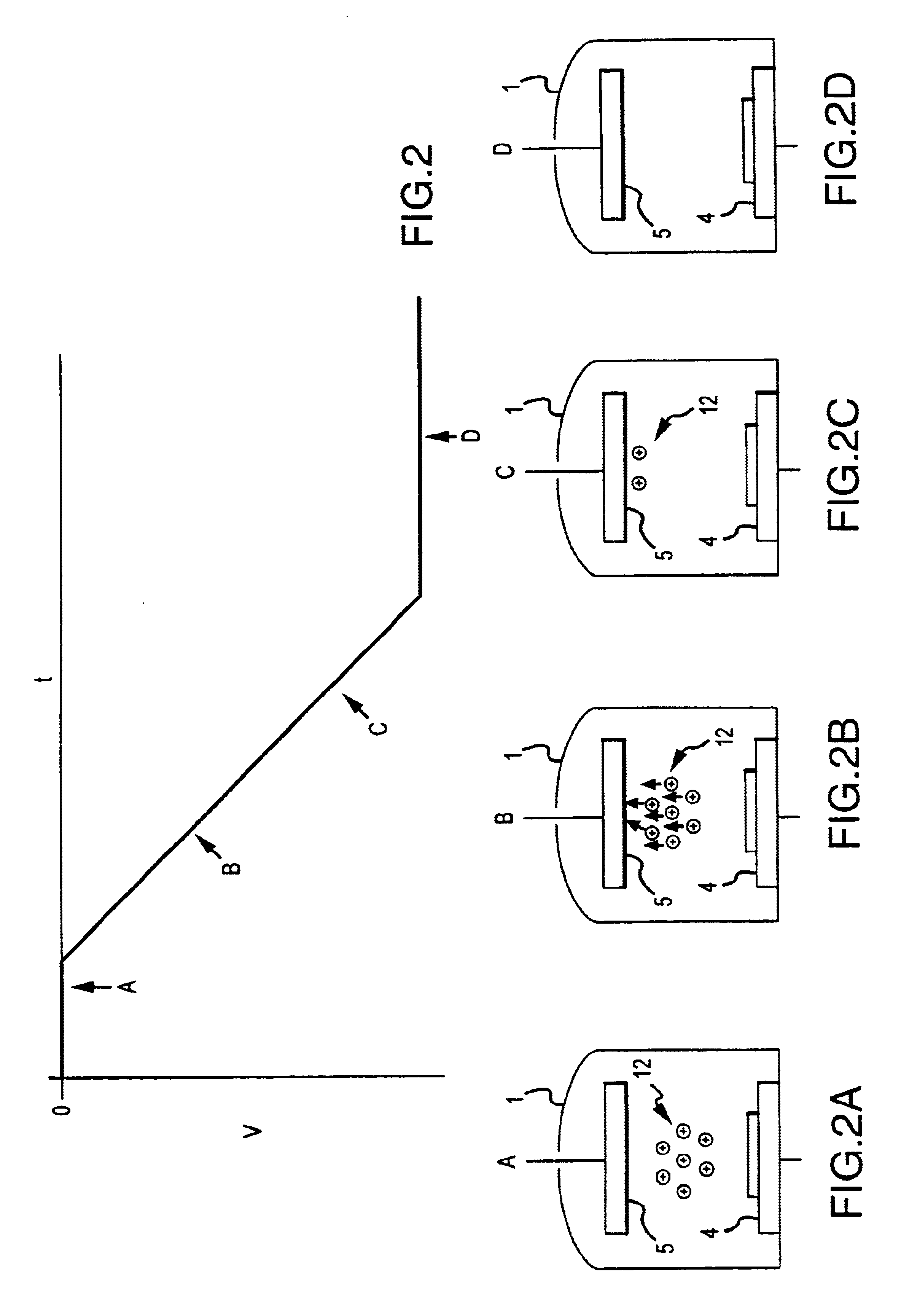
Accordingly, the present invention is directed to a system for enhancing plasma ignition through different manipulations of the voltage applied to the plasma electrodes. These manipulations can be accomplished so that a rapidly rising voltage waveform is applied to the plasma electrode. The voltage may be preferred to start at zero volts. Such a rapid rise in voltage can have a significant effect o...


PUM

PropertyMeasurementUnit
transition timeaaaaaaaaaa
timeaaaaaaaaaa
voltageaaaaaaaaaa

Abstract

An improved system of igniting a plasma using a rapid voltage rise and thus causing ions that may be pre-existing to create secondary electron emission or the like is provided. In one embodiment, the voltage rise can be timed to be comparable to the transit time of the electrons across the plasma. It can also be arranged to achieve a voltage rise in less than 1000 microseconds, to result in a transition time that is less than one hundred times the transit time, to maximize the emission of secondary electrons, or even to merely result in collision energies ranging from 5 to 500 electron volts. The transition time can be controlled through an ignition control that may be programmable, may involve charging output storage devices, or may involve delayed switching to supply the increased voltage to the plasma after the storage elements have been more fully charged.< / PTEXT>

Description

I. TECHNICAL FIELDThis invention relates to the field of plasma processing, which field comprises Physical Vapor Deposition (PVD), Plasma Enhanced Chemical Vapor Deposition (PECVD), film etching and patterning, surface modification, ashing, desmearing, and other plasma processes used in industry and research. Specifically, the invention relates to the narrower aspect of igniting a plasma in a processing system within which thin film processing is affected by the plasma.II. BACKGROUND OF INVENTIONTo begin plasma processing one must create a plasma, which is a diffuse mixture of ions and electrons, usually (but not necessarily) at a pressure less than that of a standard atmosphere. The plasma is sustained by a variety of physical mechanisms, but to begin one must create an excess of electrons or ions. In most cases the sustaining mechanism then puts energy into the system to allow the charged particles to ionize other atoms and thus build the plasma density up to a working level.As bu...

Claims


Application Information

Patent Timeline
Patent Type & Authority Patents(United States)
IPC IPC(8): H01J37/32H05H1/46
CPCH01J37/32009H05H1/46H01J37/32174H03K3/53H01J2237/3321
Inventor DRUMMOND, GEOFFREY N.MCDONOUGH, GEORGESCHOLL, RICHARD A.KERR, TIMHARPOLD, JOHN G.
Owner ADVANCED ENERGY IND INC
Why Eureka
Try Eureka