Fractional-R frequency synthesizer

a frequency synthesizer and fractional frequency technology, applied in the field of frequency synthesizers, can solve the problems of affecting the performance of the synthesizer, so as to reduce the phase noise of the synthesizer and less perturbation of the pll synthesizer

Inactive Publication Date: 2008-06-17
CSR TECH INC
View PDF6 Cites 4 Cited by
  • Summary
  • Abstract
  • Description
  • Claims
  • Application Information

AI Technical Summary

Benefits of technology

[0016]A difference between the fractional-N and the fractional-R synthesizer is the size of the steps between adjacent divider module. The smaller steps in the fractional-R synthesizer cause less perturbation of the PLL synthesizer when the divider value is switched between different states. Smaller steps result in smaller phase error correction signals at the output of the PFD, which results in lower phase noise for the synthesizer. Unlike the fractional-N synthesizer, which requires a variable integer divider, the fractional-R synthesizer requires a variable rational divider.

Problems solved by technology

This places limitations on application and design.
The flexibility of fractional-N synthesis does result in some degradation of synthesizer performance, compared to a conventional PLL 100.
This perpetual perturbation of the PLL causes excess phase noise in the spectrum of the VCO Output.
(1) Cascade or MASH Modulators: This topology is a cascade of two or more integrators or accumulators. The output of one accumulator is the input of the following. There are feed-forward paths from the overflow outputs of each accumulator to the final output, but there are no feedback paths external to the accumulators. Having no feedback is what distinguishes MASH modulators from the other types of ΣΔ modulators. It is also this property that gives MASH modulators the advantage of being unconditionally stable. MASH modulators are easy to design and implement and produce compact designs. The disadvantages of MASH modulators include: 1) the noise shaping function depends only on the order of the modular (which is equal to the number of integrators), and cannot optimized for the PLL; 2) MASH modulators always have multi-bit outputs which require multi-modulus dividers.
(2) Feedback Modulators: Feedback modulators have one or more feedback paths external to the integrators. There is usually at least one feedback path from output to the input. Feedback modulators may also have one or more feed-forward paths. As with MASH modulators, the number of integrators determines the order of the modulator. Unlike the MASH modulator there is more flexibility in the design by the choice of the feedback and forward paths and the coefficients of the feedback and feed-forward paths. Although the control of the noise shaping function is desirable, it also makes designs more complicated. Unlike the MASH modulator the feedback modulator is NOT unconditionally stable and requires careful choice of the feedback and feed-forward paths and coefficients to ensure stability. The feedback modulator may have a single bit output, which only requires a dual modulus divider, however multi-bit outputs are often used to improve the noise shaping. A generalized description of feedback type modulators is provided in reference: K. Chaos et. al, “A higher order topology for interpolative modulators for over sampling A / D converters”, IEEE Transactions on Circuits and Systems, vol. 309-318, March 1990.
Smaller steps result in smaller phase error correction signals at the output of the PFD, which results in lower phase noise for the synthesizer.

Method used


Image

  • Fractional-R frequency synthesizer
  • Fractional-R frequency synthesizer
  • Fractional-R frequency synthesizer

Examples


Embodiment Construction

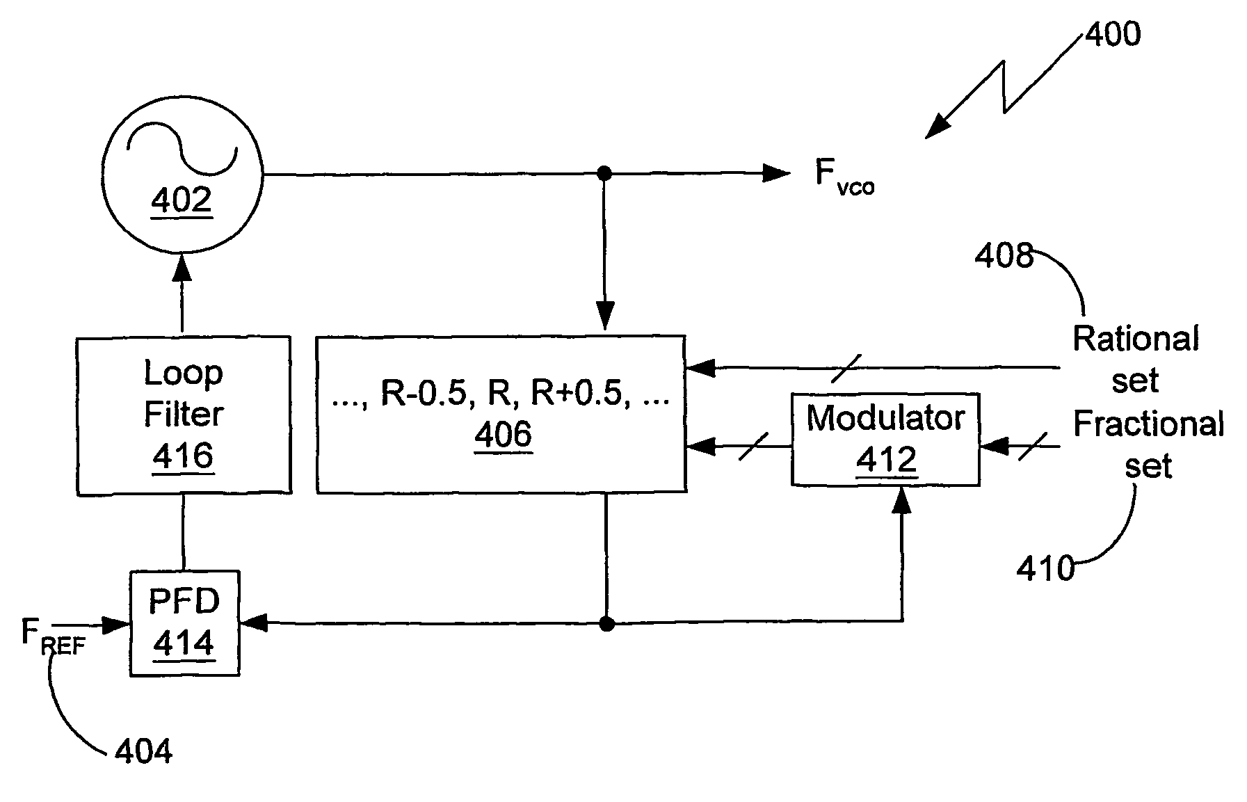
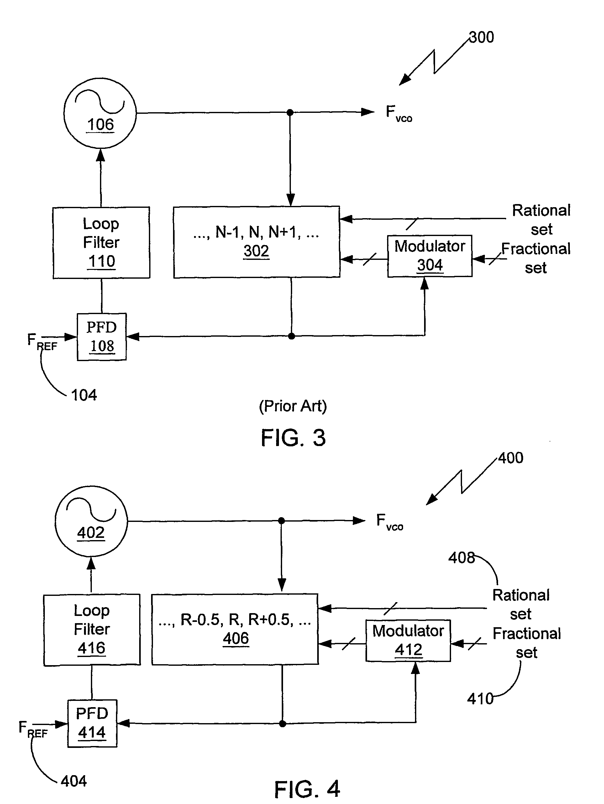
[0026]Two preferred embodiments of the fractional-R synthesizer are described. They differ in the implementation of the VCO and the rational divider. We note that a rational divider must have timing information within a fraction of a VCO cycle. If the duty cycle of the VCO Is very close to 50%, then we have timing information available every half VCO cycle. This information can be used to implement a multi-modulus divider with minimum rational steps of r=0.5. A 0.5 minimum step rational divider is described in detail in reference: M. H. Perrott, “Techniques for high data rate modulation and low power operation of fractional-N frequency synthesizers,” Ph.D. dissertation, MIT, 1997, and will be summarized in the description of FIG. 5.

[0027]To implement a divider with r<0.5 we must have access to multiple phases of the VCO, to break the VCO cycle into smaller fractions. This is possible in a ring oscillator VCO. A ring oscillator consists of a number of digital buffers connected in ser...


PUM


Abstract

A fractional-R synthesizer having a divider with rational increments and configurable in rational steps able to generate a plurality of frequencies in rational increments from a reference frequency. A voltage-controlled oscillator frequency (fVCO) is related to the reference frequency (fREF) by: fREF=fVCO / RAVG, where RAVG is the average value of the rational divide value “R” over a large number of reference cycles.

Description

CROSS-REFERENCE TO RELATED APPLICATIONS[0001]This application is a 371 of PCT / US02 / 34891, filed Oct. 31, 2002 which claims the benefit of Provisional Patent Application Ser. No. 60 / 335,678 filed on Oct. 31, 2001, and entitled “FRACTIONAL-R FREQUENCY SYNTHESIZER,” which is herein incorporated by reference.BACKGROUND OF THE INVENTION[0002]1. Field of the Invention[0003]This invention relates generally to frequency synthesizers, and in particular to fractional frequency synthesizers.[0004]2. Related Art[0005]A diagram of a conventional phase-locked loop (PLL) synthesizer 100 is shown in FIG. 1. The conventional PLL contains a fixed integer divider 102, whose modulus N provides a fixed relation between the external reference frequency fREF 104 and the internal voltage-controlled oscillator (VCO) 106 frequency fVCO. The output of the integer divider 102 is compared to the reference frequency 104 by the phase-frequency detector (PAD) 108. The PAD 108 produces an error signal, which is pro...

Claims


Application Information

Patent Timeline
Patent Type & Authority Patents(United States)
IPC IPC(8): H03D3/24G06F7/68H03L7/099H03L7/18H03L7/197
CPCG06F7/68H03L7/0995H03L7/0996H03L7/1806H03L7/1976
Inventor DUBASH, NOSHIR BEHLITSO, ROBERT
Owner CSR TECH INC
Why Eureka
Try Eureka