Modular sign post

a sign post and module technology, applied in the field of sign posts, can solve the problems of difficult installation and removal, additional cost, and heavy weight of 44 lumber sign posts, and achieve the effect of removal, and reducing the cost of installation

Inactive Publication Date: 2008-06-24
BRUMFIELD DONALD U
View PDF8 Cites 24 Cited by
  • Summary
  • Abstract
  • Description
  • Claims
  • Application Information

AI Technical Summary

Benefits of technology

[0007]The present modular sign post includes a first sign section which is mounted into the ground, a second sign section which is mounted on the first sign section, and a top arm section onto which a hanging sign may be mounted. The first sign section includes a base plate having a plurality of stakes extending from one side. In one embodiment, three stakes are used, the central stake being longer than the two flanking side stakes. On the opposite side of the base plate, a base tube is mounted. Mounted within the base plate is a guide tube. This guide tube extends into the base tube and beyond one end of the base tube. At the apex of the base tube is mounted a driving stop collar which forms an annular ring about the guide tube which extends beyond the end of the base tube. The second sign section includes a body tube having a cross-sectional interior dimension such that the guide tube may slidably fit into the body tube. A driving collar is mounted at a first end of the body tube. A flyer box mount is attached to the body tube. When the first section is placed such that the end of the stakes are pointing into the ground, the second section may be mounted over the first section and raised and lowered such that the driving collar repeatedly strikes the driving stop collar. Relatively little force is required to raise and lower this second section. This force would act to drive the stakes into the ground. Once the first sign section is mounted into the ground and the second sign section is mounted over the first a third sign section may be mounted over the second sign section. The third sign section includes a top vertical tube having a cross-sectional dimension allowing the tube to be mounted into the inner bore second tube. Mounted on this top vertical tube is an upper horizontal arm and a lower horizontal arm. The lower horizontal arm is mounted onto the top vertical tube such that it is parallel to the upper horizontal arm for most of its length. Proximate to one end of the lower arm, the arm bends and is connected to the upper horizontal arm.

Problems solved by technology

The 4×4 lumber sign posts are rather heavy and bulky to transport and challenging to install and remove.
This creates additional cost and causes a delay in placing the sign.

Method used


Image

  • Modular sign post
  • Modular sign post
  • Modular sign post

Examples


Embodiment Construction

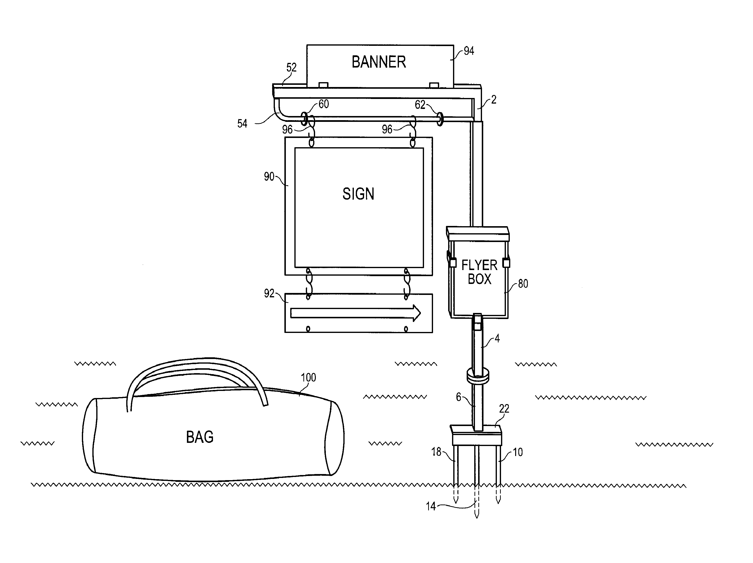
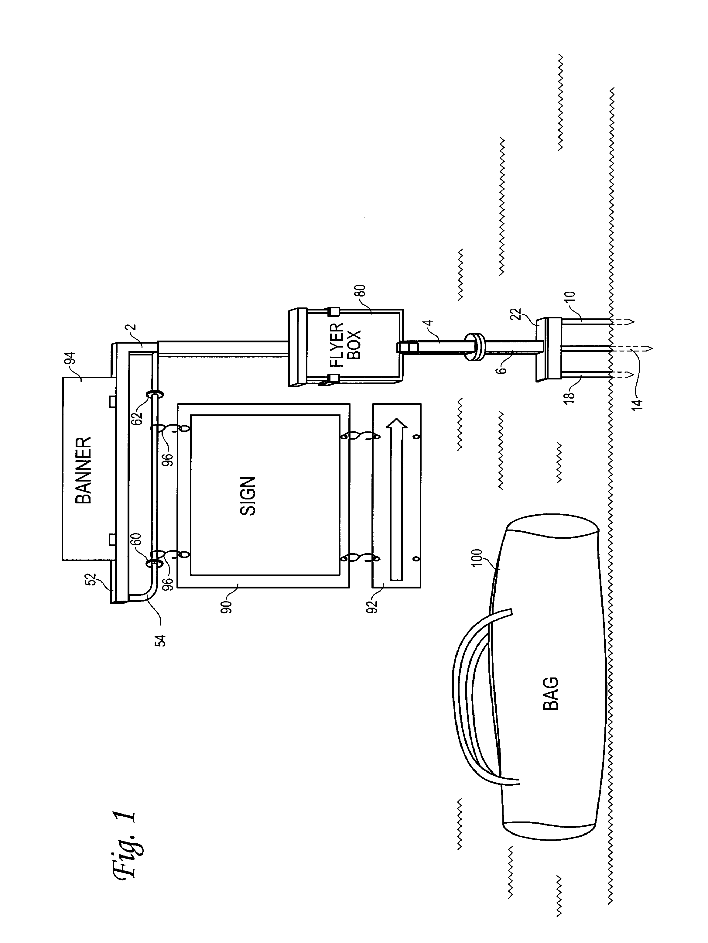
[0012]With reference to FIG. 1, an assembled modular sign is shown. This view shows a first sign section 6 having stakes 10, 14, 18, which extend from base plate 22 mounted into the ground. Fitting onto first sign section 6 is second sign section 4. Mounted on second sign section 4 is a flyer box 80. Mounted atop second sign section 4 is a third sign section 2. Extending horizontally from a vertical post on second section 2 is a upper horizontal arm 52 and a lower horizontal arm 54. Hanging from lower horizontal arm 54 between drift stops, 62 are signs held by S-hooks 96. The S-hooks are preferred to have large throat openings on the sign hanging end for easier insertion into the sign holes. On the end that hooks over the lower horizontal arm 54, the S-hook may be crimped to permanently attach the S-hook to lower horizontal arm 54. This prevents the sign from blowing off in the wind, the hook being lost in post disassembly, etc. The sign 90 may include a lower sign 92 also attached ...


PUM


Abstract

A modular signpost including a first section, a second section that mounts onto the first section, and a third section that mounts onto the second section. The first section includes a ground mounting structure, a base tube and a guide tube. The second section includes a bracket for holding a flyer box. The second section includes a body tube that is able to slide over the guide tube on the first section. The third section is slide fit into the second section.

Description

TECHNICAL FIELD[0001]The present invention relates generally to sign posts and more particular to a sign post which is modular, made to assemble from multiple sections, and can be reassembled and mounted in the ground without the use of additional tools.BACKGROUND OF THE INVENTION[0002]In real estate and a number of other fields it is very useful to have a sign post for indicating information (e.g., that a property is for sale) to the public in a conspicuous manner. Commonly the signs currently in use are usually manufactured of 4×4 lumber sections joined to form a vertical post and horizontal top arm. The signs hang from the bottom of the horizontal arm and additional banners may be placed on top of the horizontal arm. For example, the name of the real estate company and agent may be positioned on S-hooks below the horizontal arm (mounted on a ring or hook secured into the horizontal arm) while “sale pending” or other sale information may be placed at the top of the horizontal arm....

Claims


Application Information

Patent Timeline
Patent Type & Authority Patents(United States)
IPC IPC(8): G09F15/02A45F3/44A47F5/00A47G29/00B25D9/00F16M13/00G09F15/00
CPCA45F3/44G09F7/22G09F15/0037
Inventor BRUMFIELD, DONALD U.
Owner BRUMFIELD DONALD U
Why Eureka
Try Eureka