Quick connector

a quick connector and connector technology, applied in the direction of hose connections, couplings, pipe couplings, etc., can solve the problems of inability to easily remove the ring, the length of the housing of the quick connector increases inevitably, and the quick connector has problems. achieve the effect of avoiding false locking

Active Publication Date: 2008-06-24
SANOH KOGYO KK
View PDF11 Cites 51 Cited by
  • Summary
  • Abstract
  • Description
  • Claims
  • Application Information

AI Technical Summary

Benefits of technology

[0010]The quick connector disclosed in Patent document 3 avoids false locking effectively without using a long housing. A retainer included in the quick connector disclosed in Patent document 3 is provided with a restraining ring which is torn off the retainer when a tube is inserted in a housing. Then, the retainer can be pressed in the housing.
[0013]Another object of the present invention is to provide a quick connector capable of stably operating to prevent the connection of a tube to the quick connector in a falsely locked state with reliability and having compact construction.

Problems solved by technology

It is a problem in the quick connector that the end part of the tube looks as if it is completely connected to the quick connector when the retainer is pressed in the housing to its fastening position and a sealing member placed in the quick connector becomes effective when no pressure is applied thereto notwithstanding the end part of the tube is actually incompletely connected to the quick connector.
However, the length of the housing of the quick connector increases inevitably.
However, this quick connector has problems.
Practically, the length of an end part of the tube inserted in the housing varies according to force exerted on the tube to insert the tube in the housing so that the restraining ring may be torn off, the restraining ring cannot be easily torn off and hence the action of the quick connector is unstable.

Method used


Image

  • Quick connector
  • Quick connector
  • Quick connector

Examples


first embodiment

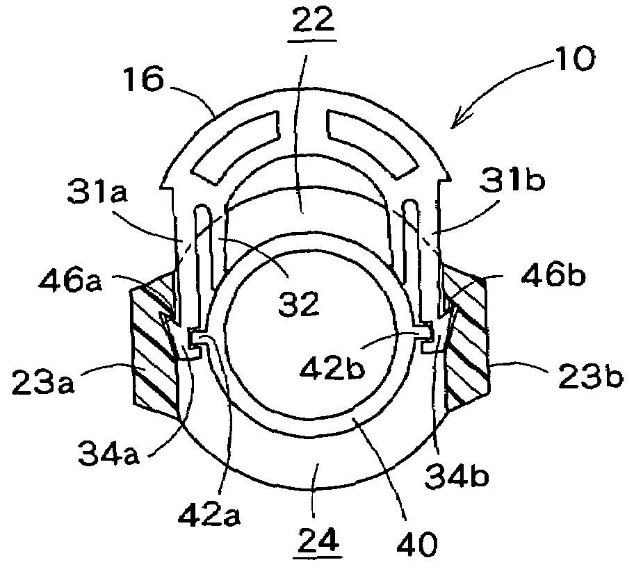
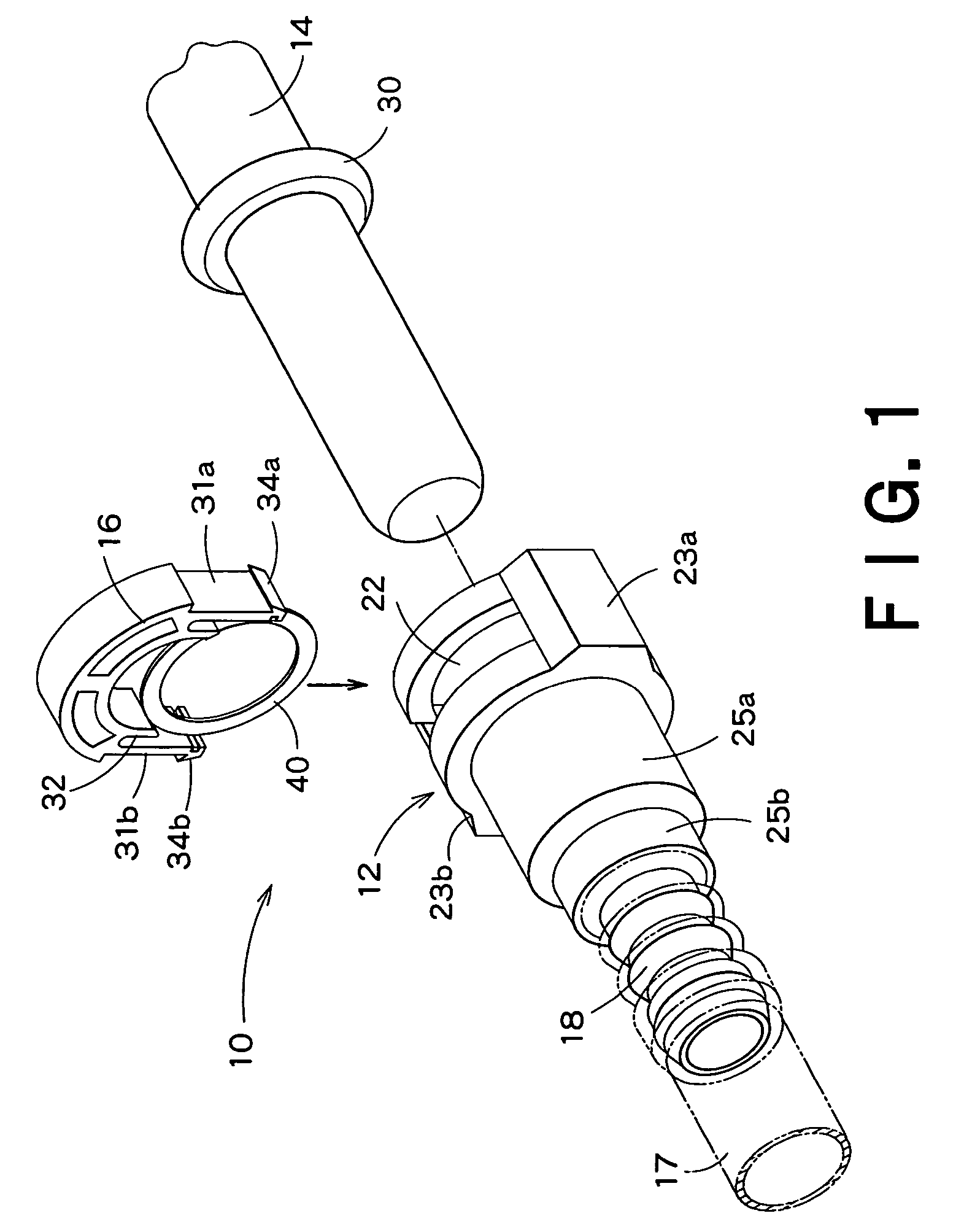
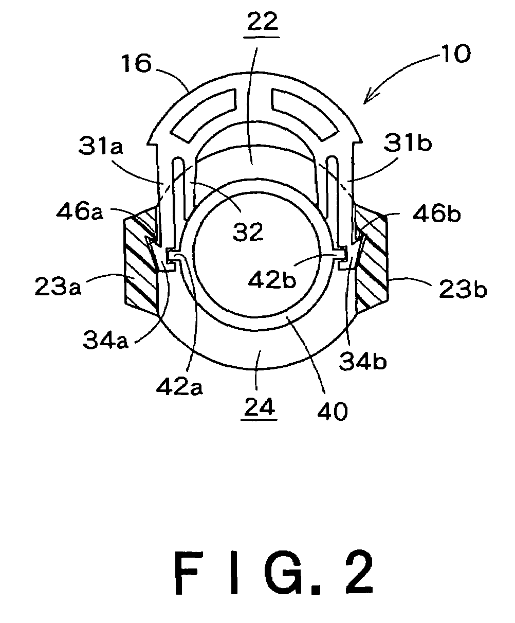
[0030]FIG. 1 is an exploded perspective view of a quick connector 10 in a first embodiment according to the present. Shown in FIG. 1 are a housing 12, a tube 14 and a retainer 16. FIG. 2 is a cross-sectional view of the housing 12 in a state where the retainer 16 is temporarily combined with the housing 12. FIG. 3A is a longitudinal sectional view of the housing 12 in a state where the tube 14 is inserted in the housing. FIG. 3B is a longitudinal sectional view of the housing 12 in a state where the retainer 16 is able to retain the tube 14 in the housing 12.

[0031]The housing 12 of the quick connector 10 is a female joint having an opening 20 through which the tube 14 is inserted in the housing 12. The housing 12 is integrally provided with a tube connector 18. The tube connector 18 is pressed in a resin tube 17. As shown in FIG. 3, the housing 12 has an axial stepped bore 21.

[0032]A circumferential upper slot 22 is formed in an upper part of the housing 12. The retainer 16 is inser...

second embodiment

[0052]FIG. 6 shows a restraining ring 50 included in a quick connector in a second embodiment according to the present invention. The locking bars 42a and 42b of the restraining ring 40 of the quick connector 10 in the first embodiment are connected to the retainer 16 by the shear fins 43a and 43b. In the quick connector in the second embodiment, a retainer 16 and the restraining ring 50 are individual members. The retainer 16 of the second embodiment is the same as the retainer 16 of the first embodiment and hence the description thereof will be omitted.

[0053]The restraining ring 50 has a small thickness and is provided, similarly to the restraining ring 40 of the first embodiment, with short locking bars 42a and 42b respectively at diametrically opposite positions. The restraining ring 50 is provided integrally with elastic pushing lugs 52a and 52b analogous with plate springs and projecting from parts, near the locking bars 42a and 42b, of the inner end surface of the restraining...


PUM


Abstract

A quick connector has a housing, a retainer for locking a tube at a correct position for complete connection in the housing and a restraining ring for restraining the retainer from being pressed into the housing to its locking position unless the tube is inserted in the housing and placed at the correct position for complete connection to avoid connecting the tube to the quick connector in a falsely locked state. The restraining ring is provided with locking bars that engage with the legs of the retainer to restrain the retainer from being pressed into the housing. The locking bars permit releasing the restraining ring to its releasing position to enable the retainer to be pressed into the housing to the locking position.

Description

TECHNICAL FIELD[0001]The present invention relates to a quick connector for connecting tubes of an automotive fuel supply system or the like.BACKGROUND ART[0002]Quick connectors are prevalently used, for example, as connectors for connecting fuel tubes of automotive fuel supply systems. A quick connector of this kind including a housing and a retainer is capable of connecting two tubes by simple operations without using any fastening means, such as bolts. The two tubes are connected simply by attaching the housing to one of the tubes, inserting an end part of the other tube in the housing and pressing the retainer into the housing. Representative prior art quick connectors are mentioned in Patent documents 1 and 2.[0003]Referring to FIG. 8, an annular ridge 3 is formed in the outer circumference of an end part of a tube 2 fitted in a housing 4. A slide retainer 5 is pressed radially in a window formed in the housing 4. An end edge 6a of a rib 6 formed in the retainer 5 engages with ...

Claims


Application Information

Patent Timeline
Patent Type & Authority Patents(United States)
IPC IPC(8): F16L39/00F16L37/12F16L37/084
CPCF16L37/144F16L2201/10Y10S285/921
Inventor MATSUBARA, SATOSHI
Owner SANOH KOGYO KK
Why Eureka
Try Eureka