Device for assembling annular flanges together, in particular in a turbomachine

a technology for assembling annular flanges and turbomachines, which is applied in the direction of couplings, liquid fuel engines, rod connections, etc., can solve the problems of not providing known means to ensure proper angular positioning, no known means are provided to warn operatives of bad angular positioning, etc., and achieves simple, effective and inexpensive effects

Active Publication Date: 2008-06-24
SN DETUDE & DE CONSTR DE MOTEURS DAVIATION S N E C M A
View PDF10 Cites 14 Cited by
  • Summary
  • Abstract
  • Description
  • Claims
  • Application Information

AI Technical Summary

Benefits of technology

[0006]The invention seeks in particular to provide a solution to this problem that is simple, effective, and inexpensive.
[0012]In both these embodiments, the peg or the stud projecting from the flange can engage in any of the notches of the other flange when the relative angular positioning between the two flanges is correct. Otherwise, the peg or the stud comes into abutment against a solid portion and prevents the two flanges from being pressed axially one against the other.

Problems solved by technology

Under such circumstances, the offset flange is not securely fastened to the other flanges since it is merely clamped axially between the other flanges, and it might move angularly or radially in the event of the fastening bolts loosening or under centrifugal forces.
No known means are provided to ensure proper angular positioning of annular fastening flanges, other than the care taken by operatives performing assembly, and no means are provided for warning operatives that angular positioning is bad.

Method used


Image

  • Device for assembling annular flanges together, in particular in a turbomachine
  • Device for assembling annular flanges together, in particular in a turbomachine
  • Device for assembling annular flanges together, in particular in a turbomachine

Examples


Embodiment Construction

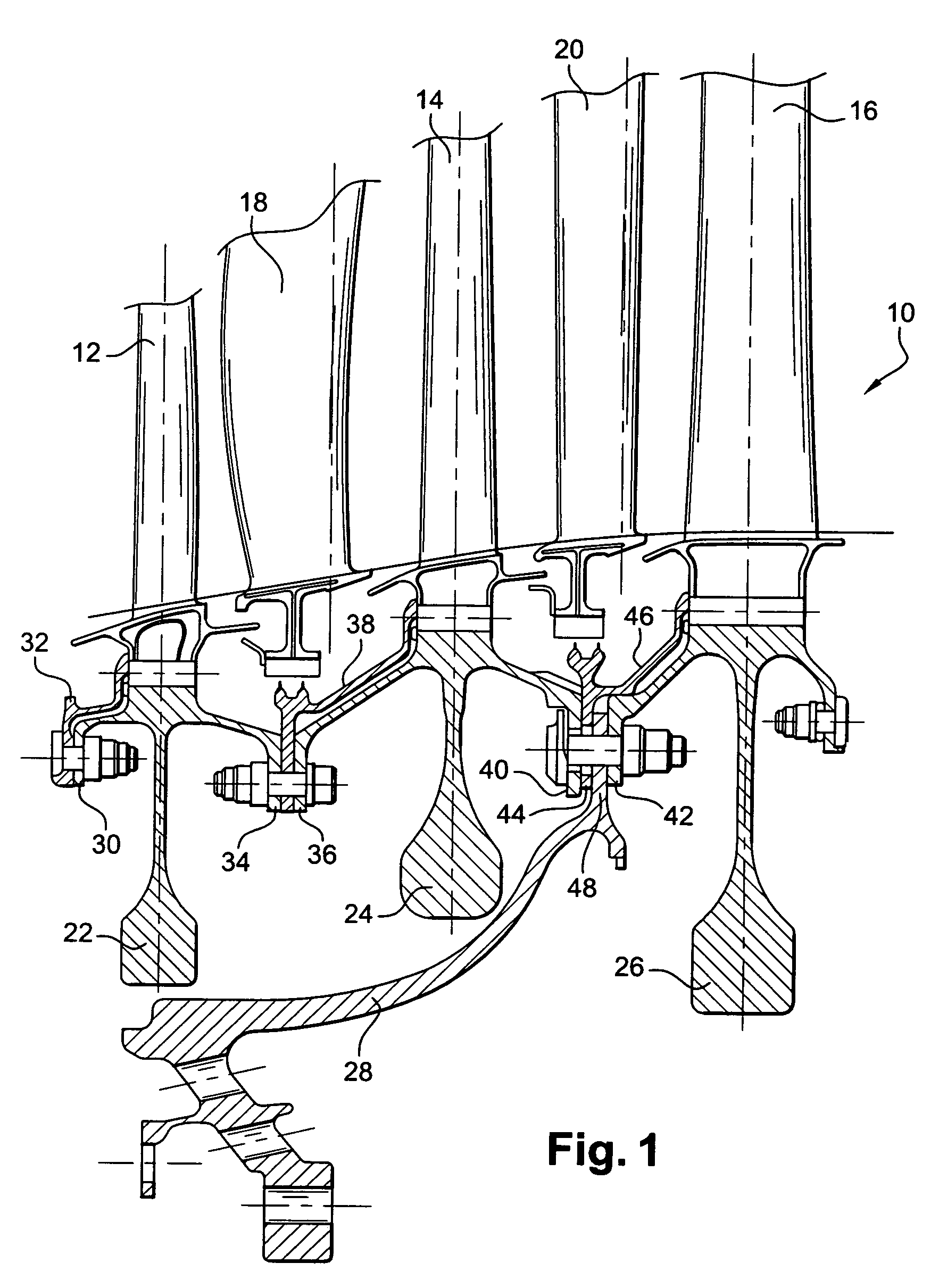
[0021]FIG. 1 is a fragmentary view of a low-pressure turbine 10 of a turbojet, having three stages of moving blades 12, 14, and 16, and two stages of stationary vanes 18, 20.

[0022]The radially outer ends of the stationary vanes 18, 20 are mounted by means (not shown) to the casing of the turbojet, and the radially inner ends of the moving blades 12, 14, and 16 are mounted by suitable means, e.g. dovetails or the like, to three disks 22, 24, and 26 of the rotor.

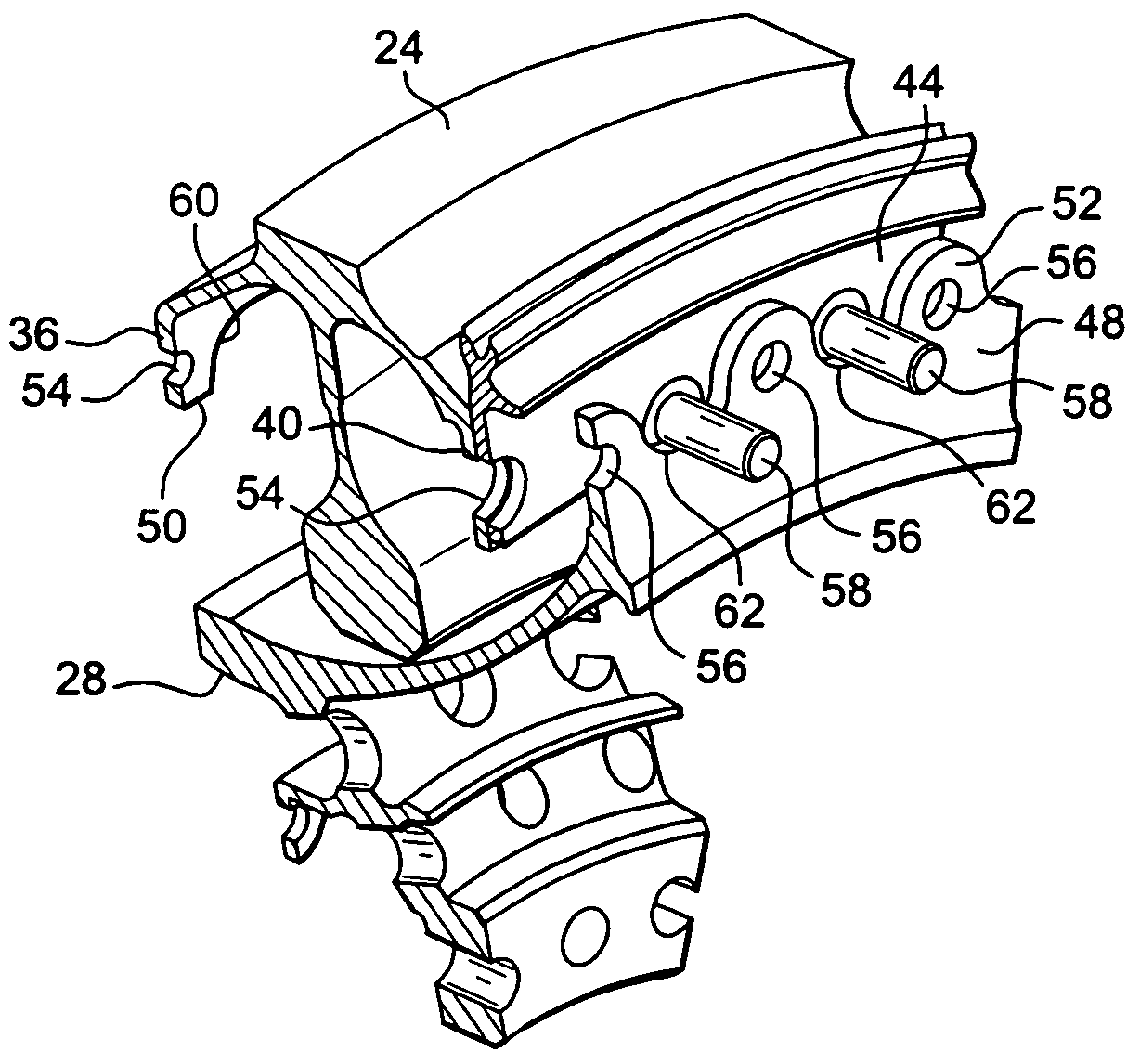
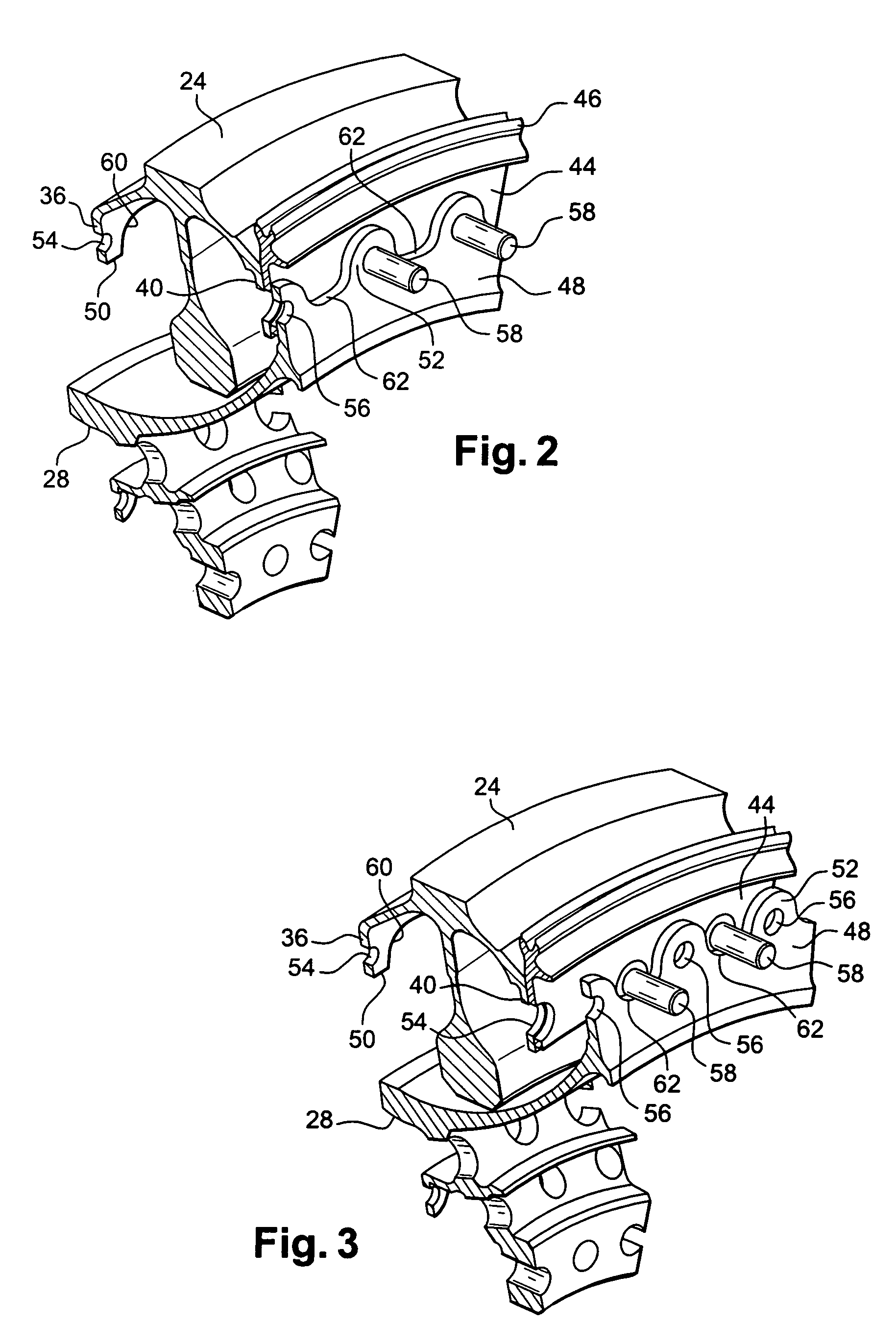
[0023]Each disk 22, 24, and 26 has an upstream annular flange and a downstream annular flange, these flanges serving for fastening the disks to one another and to a drive cone 28 connected to the shaft of the turbomachine, and also serving to fasten annuluses for retaining the blade roots on the disks.

[0024]More precisely, the upstream disk 22 has an upstream annular flange 30 having an annulus 32 fastened thereto by means of bolts, the annulus 32 serving to retain the roots of the blades 12 on the disk 22, and also has a down...


PUM

PropertyMeasurementUnit
diameteraaaaaaaaaa
shapeaaaaaaaaaa
pressureaaaaaaaaaa

Abstract

A device for assembling together annular flanges by means of fastening bolts, in particular in a low-pressure turbine stage of the turbojet, one of the flanges has an element projecting from its face that faces the other flange and that is received in a notch in said other flange when the relative angular positioning of the two flanges is correct.

Description

[0001]The invention relates to a device for assembling annular flanges together, in particular flanges for fastening together the parts of a rotor or a stator in a turbomachine.BACKGROUND OF THE INVENTION[0002]In the low-pressure turbine stages of turbojets, parts are assembled to one another by means of annular flanges pressed against one another and fastened together by bolts which pass through orifices in the annular flanges, these orifices being distributed regularly around the annular flanges.[0003]Some such flanges are “festooned”, i.e. their through orifices for fastening bolts are formed in solid portions which are separated from one another by notches giving such annular flanges a “festooned” shape, in other words a shape that is crenellated with edges that are rounded or rectangular.[0004]For a low-pressure turbine of a turbojet, the various parts are stacked vertically on one another, and they are then fastened together by means of bolts which are passed blind through the...

Claims


Application Information

Patent Timeline
Patent Type & Authority Patents(United States)
IPC IPC(8): F01D25/00F01D5/06F01D25/24F01D25/28F02C7/00F16B7/18F16D1/033F16L23/036
CPCF16L23/036F01D5/066F05D2260/31Y10T29/53
Inventor CHARRIER, EMMANUELSOUPIZON, JEAN-LUC
Owner SN DETUDE & DE CONSTR DE MOTEURS DAVIATION S N E C M A
Why Eureka
Try Eureka