Multi-port suction reed valve with optimized tips

a suction reed valve and multi-port technology, applied in the direction of machines/engines, liquid fuel engines, positive displacement liquid engines, etc., can solve problems such as valve failure, minimize the distance between the axes, shorten the span from the pins to the tips, and minimize the effects of transverse bending

Active Publication Date: 2008-06-24
CARRIER CORP
View PDF7 Cites 16 Cited by
  • Summary
  • Abstract
  • Description
  • Claims
  • Application Information

AI Technical Summary

Benefits of technology

[0003]For multi-port suction valves, each valve tip and the associated tip recess are located along lines extending from the axis of the cylinder through the axis of the associated suction port. This arrangement minimizes the distance between the axis of each suction port and the tip recess and places the load due to flow through the suction ports as close as possible to the cylinder wall tip support thereby minimizing the effects of transverse bending while shortening the span from the pins to the tips. This combination yields the valve with the lowest maximum stress.

Problems solved by technology

Because the valve tips are located near the suction ports and because the valve tips are in a nominal line contact with the housing structure, the valve tips tend to be stressed which can result in valve failure by permitting the valve to be drawn into the cylinder.

Method used


Image

  • Multi-port suction reed valve with optimized tips
  • Multi-port suction reed valve with optimized tips
  • Multi-port suction reed valve with optimized tips

Examples


Embodiment Construction

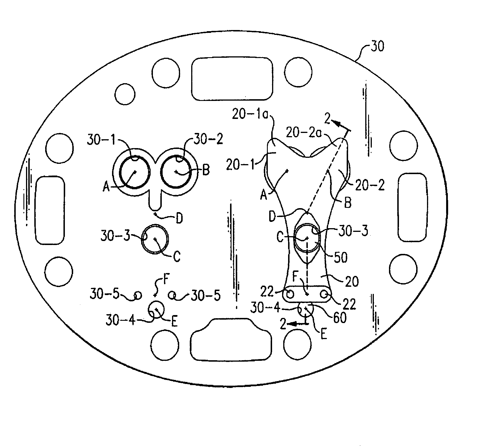
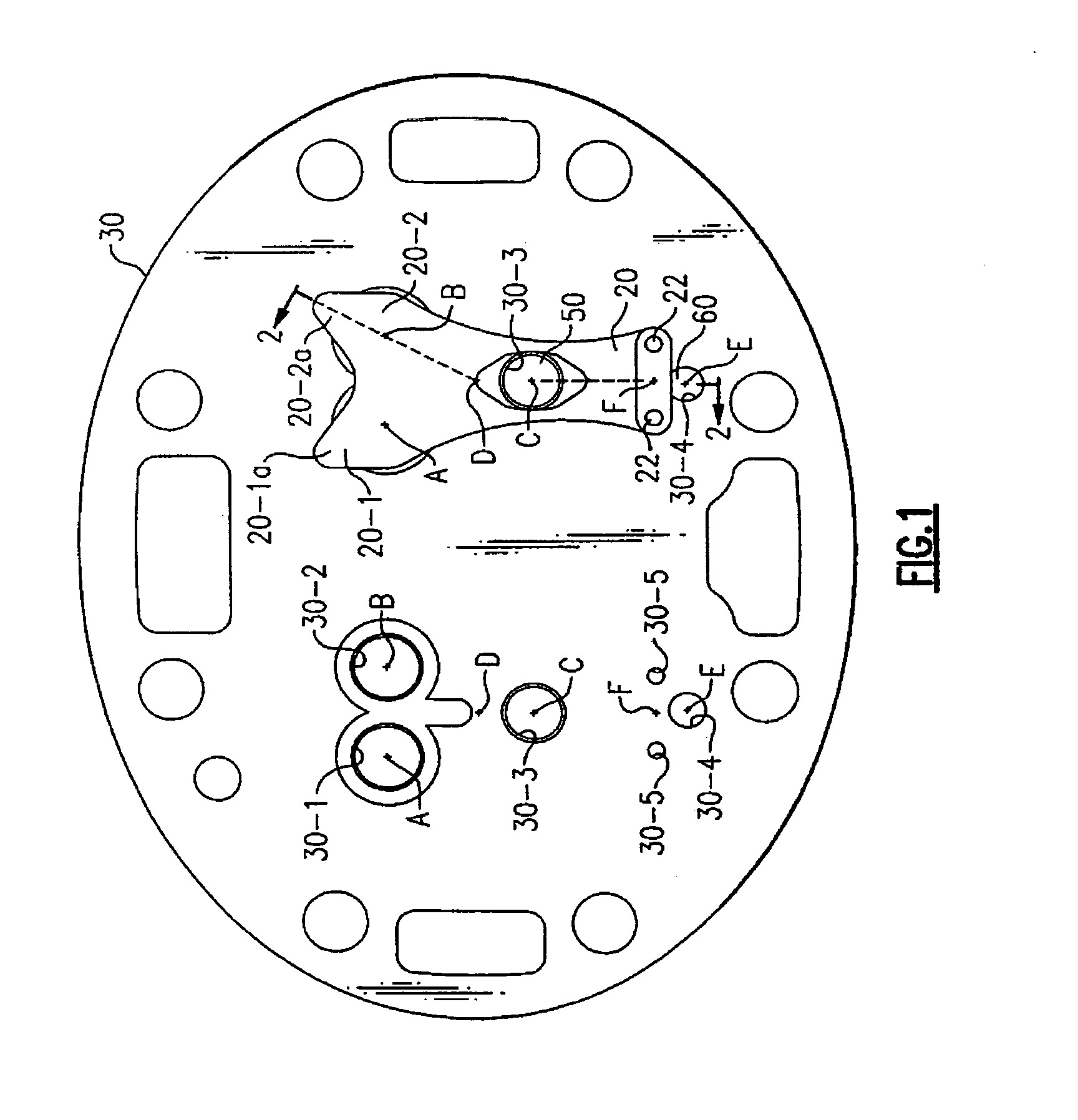
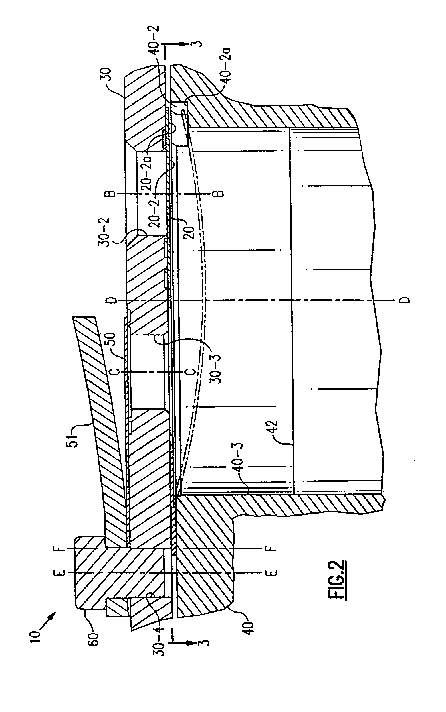
[0011]In FIGS. 1 and 2, the numeral 30 generally designates a valve plate associated with two cylinders of a reciprocating compressor. Two, or more, suction passages 30-1 and 30-2 having axes A and B, respectively, and at least one discharge passage 30-3 having an axis C are associated with each cylinder. The point D corresponds to the axis of a cylinder. The point E corresponds to the axis of the bore 30-4 and pin / bolt 60 holding valve plate 30, and discharge valve 50 in place when a single bolt 60 is used. If more than one bolt 60 is used, axis E would be at a mid-point of a line going through their centers. Pins 22 are received in bores 30-5 and secure suction valve 20 in place. Axis F is the mid-point between the axes of pins 22 and their bores 30-5 for each suction valve 20. The axes A, B, C, D, E and F are illustrated as points or lines, even in the absence of the related structure, because of their relationships relative to the present invention. Referring specifically to FIG...


PUM


Abstract

A reed valve having a plurality of tips and associated recesses is provided as a compressor suction valve with each valve tip coacting with a suction port. The recesses are located in the housing structure defining the cylinder of the compressor and are spaced a distance on the order of 0.1 inches from the tips when the suction valve is closed. The valve is secured on one side of the cylinder and each tip is located along a line from the center of the cylinder through the center, or axis, of a suction port.

Description

BACKGROUND OF THE INVENTION[0001]A typical reciprocating compressor will have a valve plate with one, or more, suction ports and discharge ports formed therein. Normally the Suction and discharge valves will be of the same general type. Each valve would be normally closed and would open due to a pressure differential across the valve in the direction of opening. Since suction valves open into the compression chamber / cylinder they generally do not have valve backers in order to minimize the clearance volume and thus deflection of the valve is not physically limited. When a suction valve opens, the valve lip(s) engage recess(es) in the housing structure defining the piston cylinder after a small amount of opening movement with further opening being due to flexure of the valve away from the valve seat and into the cylinder.[0002]The resilience of the suction valves and adherence of the valve to the valve seat due to an oil film (“stiction”) resists the opening of the suction valve. The...

Claims


Application Information

Patent Timeline
Patent Type & Authority Patents(United States)
IPC IPC(8): F04B39/10F04B53/10F16K15/00
CPCF04B39/1073Y10T137/7891Y10T137/7859Y10T137/784F04B39/10F16K15/16F16K15/1402
Inventor MACBAIN, SCOTT M.DUPPERT, RONALD J.
Owner CARRIER CORP
Why Eureka
Try Eureka