Cable connector with anti cross talk device

Inactive Publication Date: 2008-06-24
HON HAI PRECISION IND CO LTD
View PDF10 Cites 32 Cited by
  • Summary
  • Abstract
  • Description
  • Claims
  • Application Information

AI Technical Summary

Benefits of technology

[0006]Accordingly, an object of the present invention is to provide an

Problems solved by technology

However, cross talk problem often occurs at interface section of the

Method used


Image

  • Cable connector with anti cross talk device
  • Cable connector with anti cross talk device
  • Cable connector with anti cross talk device

Examples


Embodiment Construction

[0015]Reference will now be made in detail to the preferred embodiment of the present invention.

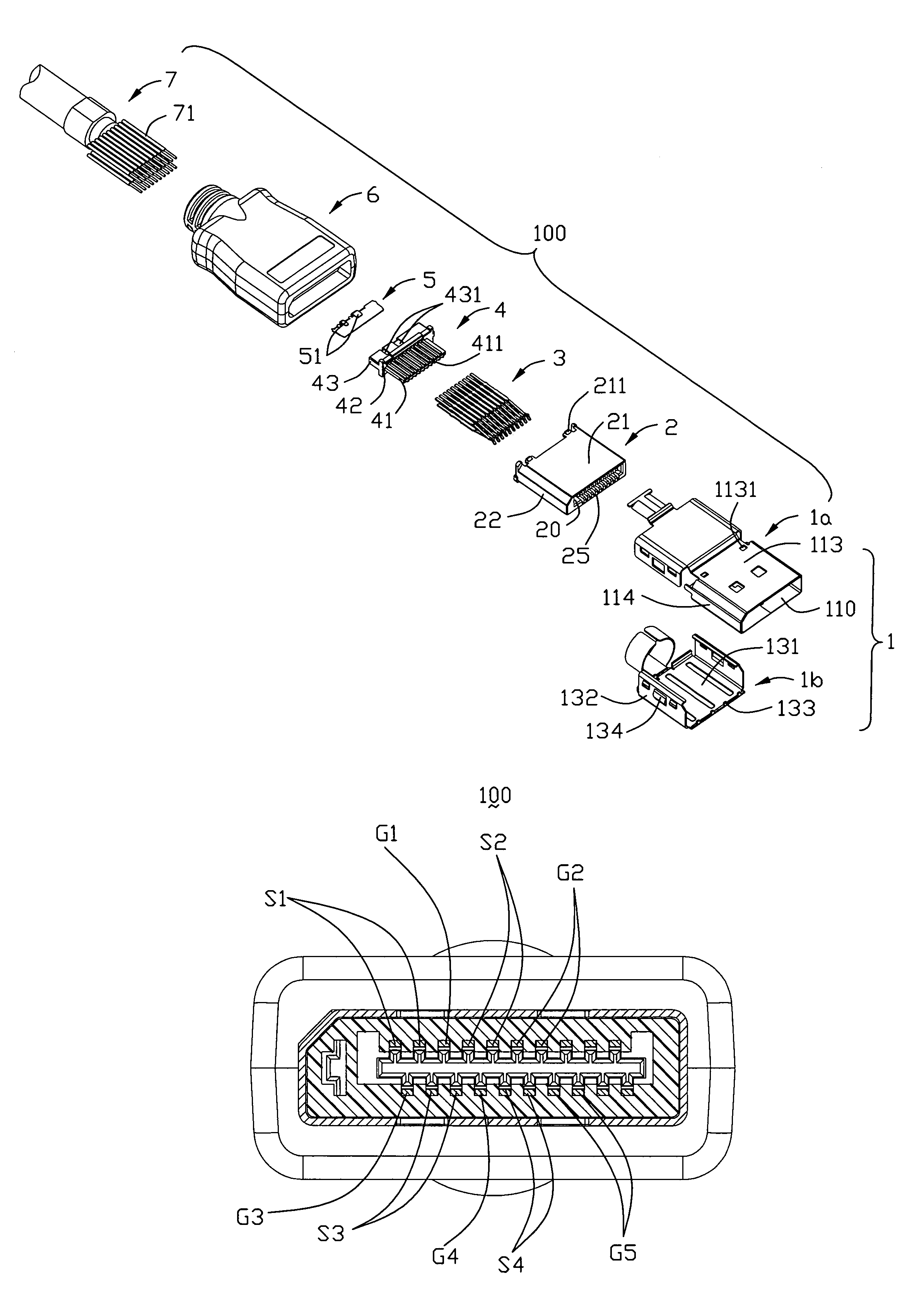
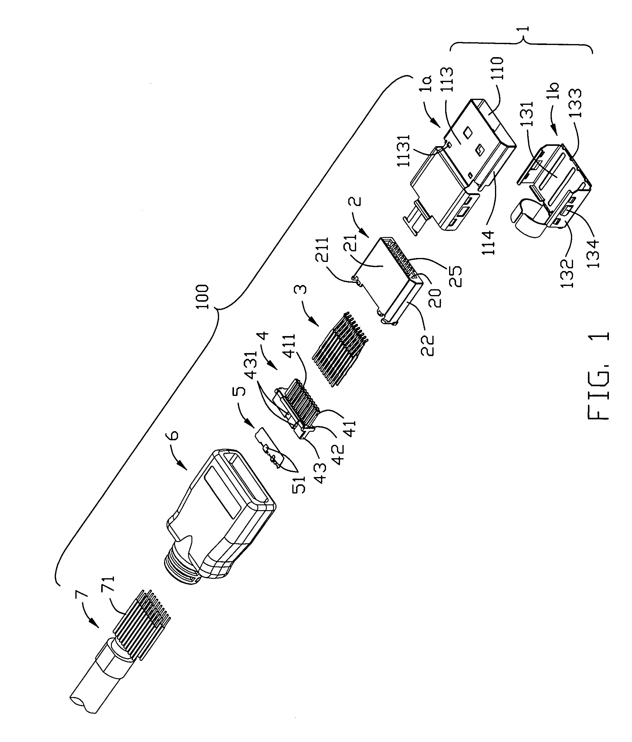
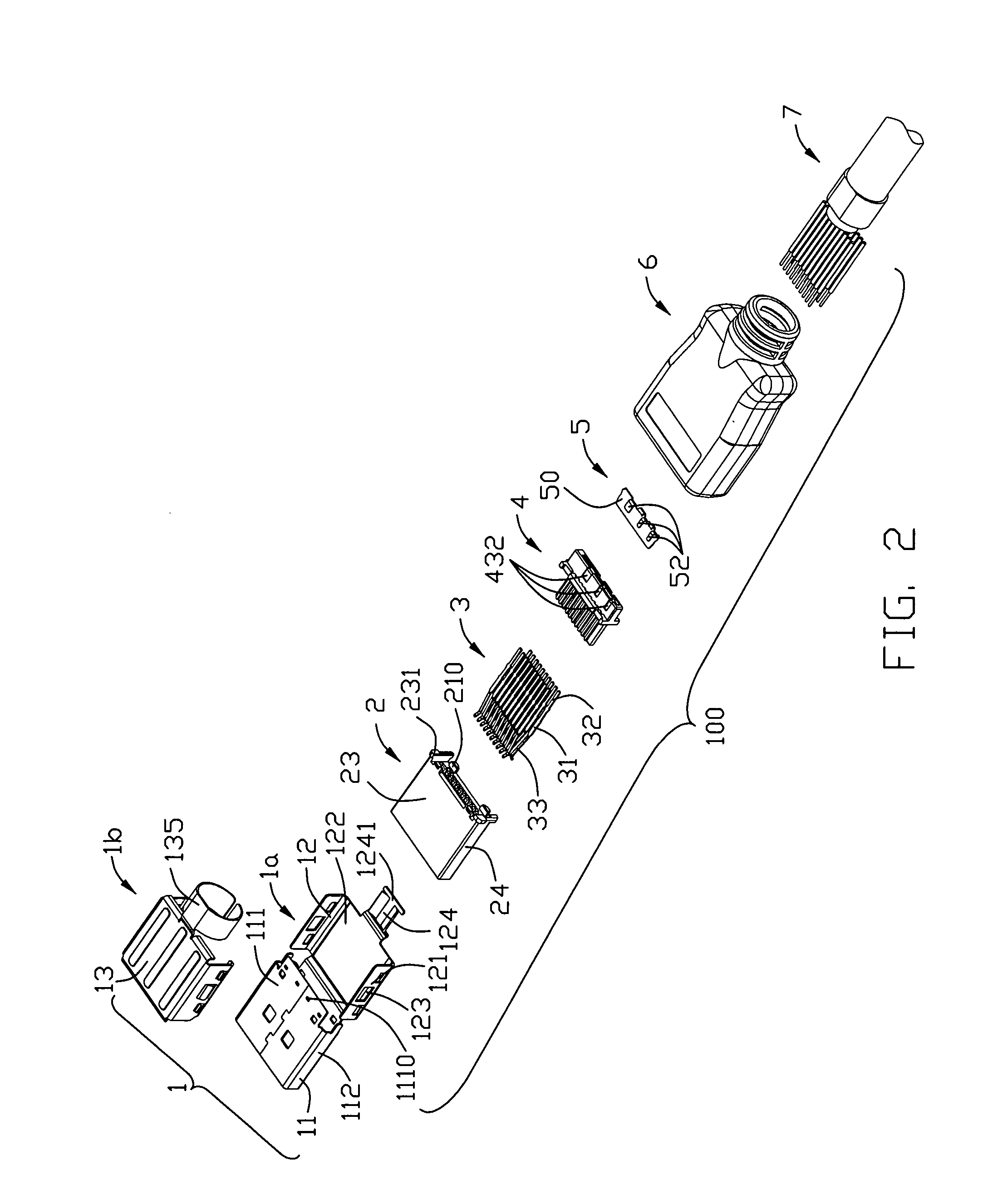
[0016]Referring to FIGS. 1-6, a cable connector 100 in accordance with the present invention comprises an insulated housing 2, a plurality of terminals 3 arranged on a spacer 4 and then together received in the insulated housing 2, a metal plate 5 embedded in the spacer 4, a metal shell 1 enclosing the insulated housing 2, a cable 7 with a number of wires 71 respectively electrically joining to the terminals 3, and a cover 6 partially over molded the metal shell 1, the insulated housing 2, the spacer 4 and the cable 7.

[0017]The metal shell 1 comprises an upper first shield portion 1a and a lower second shield portion 1b. The upper first shield portion 1a includes an enclosing portion 11 which consists of a bottom side 111, an opposite top side 113, and a pair of transversal sides 112, 114 interconnecting the top and the bottom sides 113, 111 to form a hollow 110 for receiving the insulate...


PUM


Abstract

A cable connector (100) includes an insulated housing (2) defining a receiving space (20), a plurality of terminals (3) being arranged into an upper and a lower terminal rows and received in the insulated housing (2), a metal plate (5) disposed between the upper terminal row and the lower terminal row, and a cable (7) including a number of wires electrically connecting to the terminals (3) and the metal plate (5).

Description

BACKGROUND OF THE INVENTION[0001]1. Field of the Invention[0002]The present invention generally relates to a cable connector, and more particularly to a cable connector used in high-speed signal transmission.[0003]2. Description of Related Art[0004]In recent years, human has benefited much from the fast developing digital industry. The digital industry brings us a multiply of products, such as personal computer (PC) and consumer electronic (CE) products including TV, DVD player, game console, etc. Usually, either PC or CE product has a display for showing video, and a cable connector is needed to connect an interface of the display and a control device. A display port connector may be an ideal I / O port adapted for both PC and CE product. However, cross talk problem often occurs at interface section of the display port connector, which may influence the quality of signals.[0005]Hence, an improved cable connector is highly desired to overcome the aforementioned problems.SUMMARY OF THE...

Claims


Application Information

Patent Timeline
IPC IPC(8): H01R13/648
CPCH01R9/03H01R13/6471H01R13/6585H01R13/6592Y10S439/939
Inventor WU, JERRY
Owner HON HAI PRECISION IND CO LTD
Why Eureka
Try Eureka