Method for relaying of relay having multiple antenna in wireless communication system

a wireless communication system and relay technology, applied in the field of wireless communication, can solve the problems of short time delay, noise propagation or amplification of the delivered signal, and achieve the effect of improving the quality of signal transmission

Inactive Publication Date: 2011-07-21
LG ELECTRONICS INC
View PDF7 Cites 20 Cited by
  • Summary
  • Abstract
  • Description
  • Claims
  • Application Information

AI Technical Summary

Benefits of technology

When multiple antennas are applied to a relay station operating in an amplify and forward (AF) mode, an internal connection relation of the relay station is properly controlled so that an overall channel state is satisfactorily set. Accordingly, quality of signal transmission can be enhanced.

Problems solved by technology

The AF mode has an advantage in that a time delay is short in signal delivery, but has a disadvantage in that noise is propagated or amplified in the delivered signal.
On the other hand, the DF mode has an advantage in that noise can be removed from the signal, and reliability of signal transmission can be enhanced, but has a disadvantage in that a time delay may occur in signal delivery since a demodulation and decoding process is performed.
Accordingly, there is a problem in that the conventional MIMO technique cannot be directly applied.

Method used


Image

  • Method for relaying of relay having multiple antenna in wireless communication system
  • Method for relaying of relay having multiple antenna in wireless communication system
  • Method for relaying of relay having multiple antenna in wireless communication system

Examples


Embodiment Construction

Hereinafter, exemplary embodiments of the present invention will be described in detail with reference to the accompanying drawings.

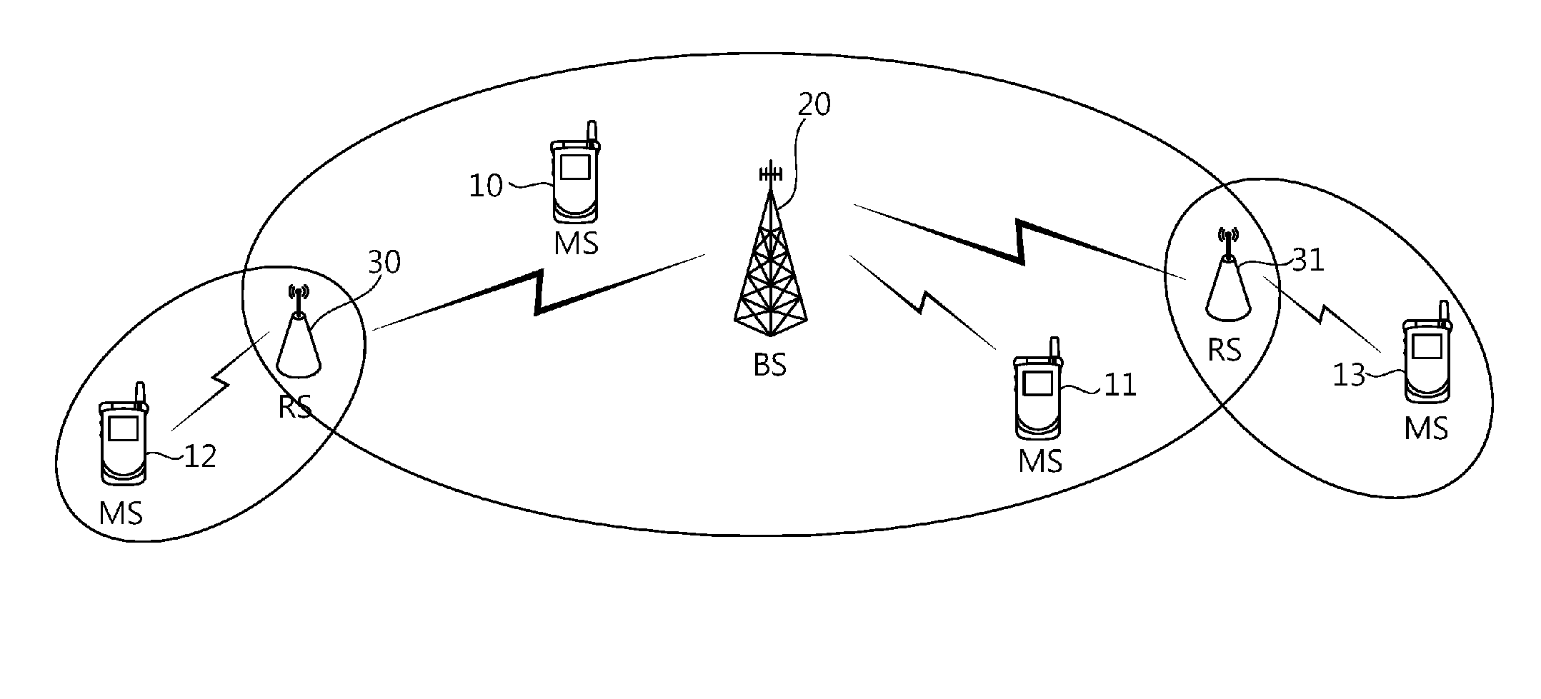
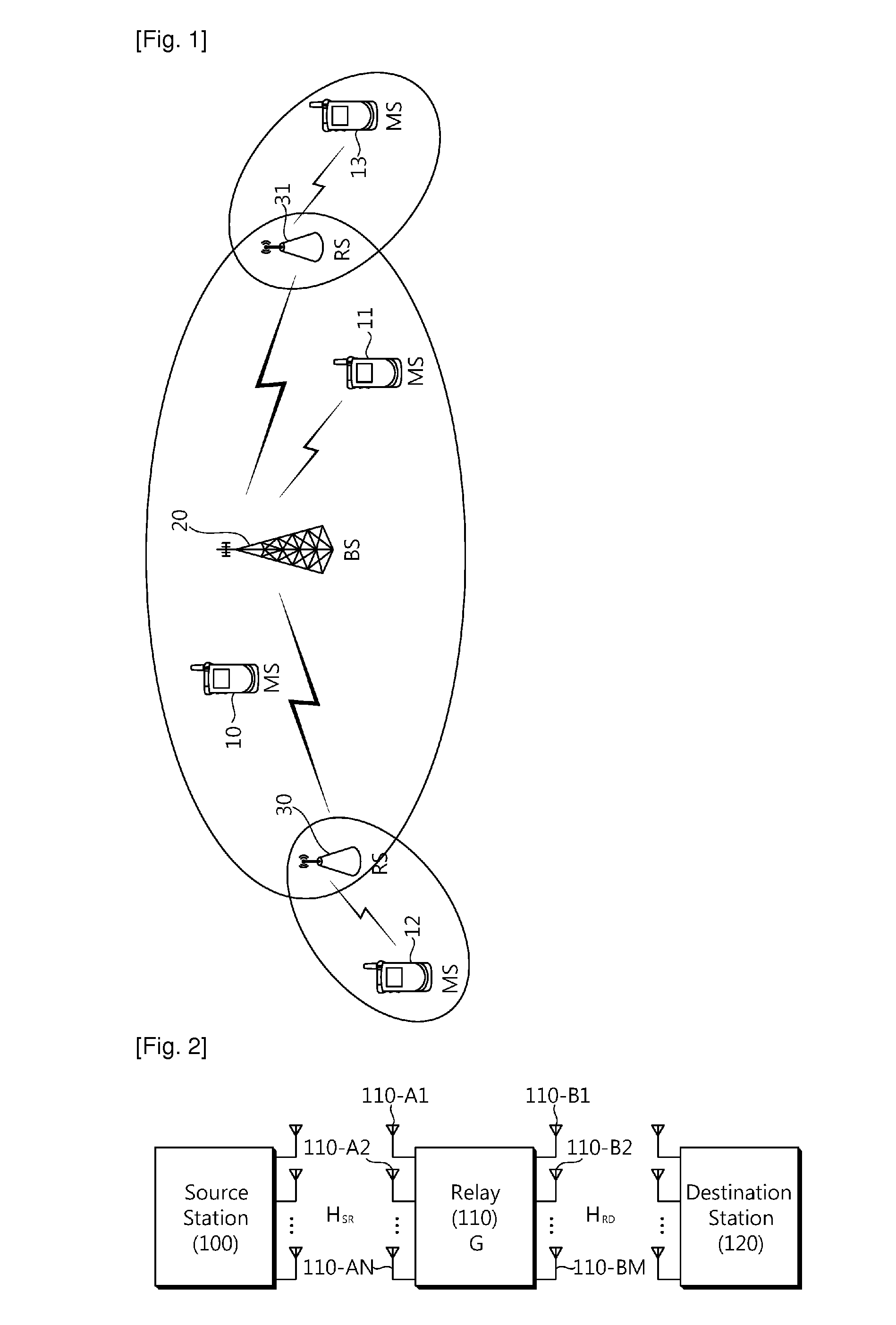
FIG. 1 is a diagram showing a wireless communication system using a relay station.

The wireless communication system can be widely deployed to provide a variety of communication services, such as voices, packet data, etc.

Referring to FIG. 1, the wireless communication system includes mobile stations (MSs) 10, 11, 12, and 13, a base station (BS) 20, and relay stations (RSs) 30 and 31. Each of the MSs 10, 11, 12, and 13 may be fixed or mobile, and may be referred to as another terminology, such as a user equipment (UE), a user terminal (UT), a subscriber station (SS), a wireless device, etc. The BS 20 is generally a fixed station that communicates with the MSs 10, 11, 12, and 13 and may be referred to as another terminology, such as a node-B (NB), a base transceiver system (BTS), an access point, etc. One or more cells may exist for one BS 20. The RSs 30 a...


PUM


Abstract

A method for relaying performed by a relay station is provided. The method includes receiving a signal from a source station through at least one receive antenna, defining a connection structure between the at least one receive antenna and at least one transmit antenna, processing the signal by using a midcoding matrix, and transmitting the processed signal to a destination station through the at least one transmit antenna. Quality of signal transmission can be enhanced.

Description

TECHNICAL FIELDThe present invention relates to wireless communications, and more particularly, to a wireless communication system employing a relay station having multiple antennas.BACKGROUND ARTThe institute of electrical and electronics engineers (IEEE) 802.16 standard provides a technique and protocol for supporting broadband wireless access. The standardization had been conducted since 1999 until the IEEE 802.16-2001 was approved in 2001. The IEEE 802.16-2001 is based on a physical layer of a single carrier (SC) called ‘WirelessMAN-SC’. The IEEE 802.16a standard was approved in 2003. In the IEEE 802.16a standard, ‘WirelessMAN-OFDM’ and ‘WirelessMAN-OFDMA’ are further added to the physical layer in addition to the ‘WirelessMAN-SC’. After completion of the IEEE 802.16a standard, the revised IEEE 802.16-2004 standard was approved in 2004. To correct bugs and errors of the IEEE 802.16-2004 standard, the IEEE 802.16-2004 / Cor1 (hereinafter, IEEE 802.16e) was completed in 2005 in a fo...

Claims


Application Information

Patent Timeline
Patent Type & Authority Applications(United States)
IPC IPC(8): H04B7/14
CPCH04B7/1555H04B7/0413
Inventor SEO, HAN BYULKIM, BYOUNG HOON
Owner LG ELECTRONICS INC
Why Eureka
Try Eureka