Combination valve

a technology of combinator valve and valve body, which is applied in the direction of mechanical equipment, functional valve types, transportation and packaging, etc., can solve the problems of difficult to achieve fine adjustment of the pressure setting of the combinator valve, unnecessary cost and waste, etc., and achieves the effect of simplifying the assembly thereof, reducing the required space, and improving fluid flow

Active Publication Date: 2008-07-01
PARKER INTANGIBLES LLC
View PDF9 Cites 45 Cited by
  • Summary
  • Abstract
  • Description
  • Claims
  • Application Information

AI Technical Summary

Benefits of technology

[0006]Accordingly, in order to overcome the deficiencies of the prior art devices, the present invention provides an improved combination valve structure that includes a check valve and a pressure relief valve for regulating the pressure of fluid flow and direction between a first fluid side and a second fluid side within a hydraulic circuit. This construction minimizes the required space, simplifies the assembly thereof, and improves fluid flow as well as reducing product cost.
[0009]In another version, the second and fourth portions of the spring cap each have an outer diameter greater than that of the intermediate third portion, thereby providing axial boundaries that facilitate the correct placement of a tool for crimping the third portion.
[0025]In another version, the second and fourth portions of the spring cap each have an outer diameter greater than that of the intermediate third portion, thereby providing axial boundaries that facilitate the correct placement of a tool for crimping the third portion.

Problems solved by technology

Some prior art designs that utilize crimping to lock the spring cap to the valve stem do not utilize a positive engagement mechanism between the spring cap and the valve stem prior to the noted crimping process.
As a result, the spring cap can axially move, thus making the fine adjustment of the relief valve pressure setting difficult to achieve.
The crimping process of the valve cap to the valve stem has to be carried out prior to the testing of the valve and if the valve, after test, does not meet the expected pressure setting, it is discarded, resulting in unnecessary cost and waste.
However, none of these prior art structures pertain to the use of a spring cap that utilizes four successively adjoining axial portions, each of which has a particular specific function, in combination with an axially, centrally apertured, valve seat that also utilizes a first plurality of axial cross-port orifice holes, all having substantially the same diameter, and a second plurality of circumferentially-spaced, radial, semicircular holes emanating from the valve seat central aperture, wherein the first and second pluralities of holes are perpendicular to and intersect each other.

Method used


Image

  • Combination valve
  • Combination valve
  • Combination valve

Examples


Embodiment Construction

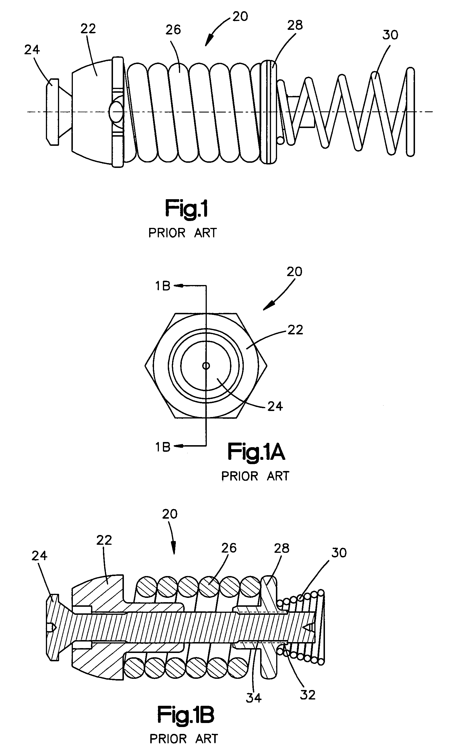
[0046]Referring now to the several drawings, illustrated in FIGS. 1, 1A and 1B, is a typical prior art combination or relief valve 20, generally manufactured from high strength steel, which basically consists of a valve seat 22, a valve stem 24, a relief valve spring 26, a spring cap 28, and a check valve spring 30, together with an optional valve plug (not shown but similar to valve plug 52 of FIG. 5) for confining check valve spring 30. Valve 20 can be provided with differing relief pressure settings, depending upon the size of the relief valve opening and the preload of relief valve spring 26. Adjusting the working height of relief valve spring 26 can change the noted pressure setting during the valve assembly. After the pressure setting has been accomplished, i.e., with relief valve spring 26 compressibly interposed between valve seat 22 and spring cap 28, spring cap 28 is locked or fixedly secured onto valve stem 24. The methods employed for locking spring cap 28 onto valve ste...


PUM


Abstract

Improvement in a combination valve including check valve and pressure relief valve portions for regulating fluid flow pressure and direction in a hydraulic circuit, wherein a valve seat includes, in addition to a central aperture, a plurality of peripherally-spaced axial cross-port orifice holes, of same or differing diameter and a plurality of intersecting, circumferentially-spaced, radial, semicircular holes; a spring cap including four adjoining axial portions of differing outer diameters, with a first portion being a protrusion that locates an end of a relief valve compression spring, a second portion having flat outer tool locating surfaces used for rotating the spring cap for axial adjustment relative to a valve stem, a third portion having a reduced radial wall thickness for easy crimping thereof relative to a valve stem, and a fourth portion having a coaxial recess for centering and physically retaining one end portion of a check valve compression spring.

Description

CROSS-REFERENCE TO RELATED CASES[0001]The present patent application claims the benefit from the filing date of U.S. Provisional Application No. 60 / 632,280, filed Dec. 1, 2004, the disclosure of which is incorporated herein by reference.FIELD OF THE INVENTION[0002]The present invention pertains to a combination valve, including check valve and pressure relief valve portions, for regulating the pressure of fluid flow between first and second fluid portions within a hydraulic circuit. More particularly, the invention pertains to a combination valve that utilizes an improved spring cap and an improved valve seat in combination with a valve plug, a valve stem, a check valve compression spring, and a relief valve compression spring.BACKGROUND OF THE INVENTION[0003]Hydrostatic transmissions have many and varied uses, including the propelling of vehicles, such as mowing machines, and offer stepless control of such a machine's speed. A typical hydrostatic transmission system includes a vari...

Claims


Application Information

Patent Timeline
Patent Type & Authority Patents(United States)
IPC IPC(8): F16K17/196
CPCF16K17/26F16K17/048F16K17/196Y10T137/778Y10T137/7777
Inventor DONG, XINGENELLENBURG, ALBERT C.HOLZSCHUH, FRANK P.
Owner PARKER INTANGIBLES LLC
Why Eureka
Try Eureka