Electronic product identifier system

a product identification and electronic technology, applied in the field of electronic displays, can solve the problems of not being able need some form of manual intervention, fragile, etc., and achieve the effect of reducing the size and ability of the display system to withstand the environment of a retail stor

Active Publication Date: 2008-07-01
IRIS OPTRONICS CO LTD
View PDF37 Cites 44 Cited by
  • Summary
  • Abstract
  • Description
  • Claims
  • Application Information

AI Technical Summary

Problems solved by technology

One major disadvantage of prior systems is that they need some form of manual intervention to ensure that the electronic shelf labels are positioned at the appropriate places on the shelves.
Another limitation of existing electronic shelf labels systems is that the display systems used in electronic shelf labels have very limited functionality.
Further, most display systems used in electronic shelf labels are based on glass cells, which means that they are fragile and have severe limitations for size and ability to withstand the environment of a retail store.
Accordingly, the value of an automatic price update capability is severely limited.
The major deficiency of the '593 application publication is that it relies upon the store operations personnel being familiar with the desired stock locations and stocking the shelves appropriately.
However in reality, the operation of the store is such that it is not always possible or desirable to dictate the location of items from a central office.
In cases where items are out of stock, it becomes difficult to place substitute items because price information would be incorrect.

Method used


Image

  • Electronic product identifier system
  • Electronic product identifier system
  • Electronic product identifier system

Examples


Embodiment Construction

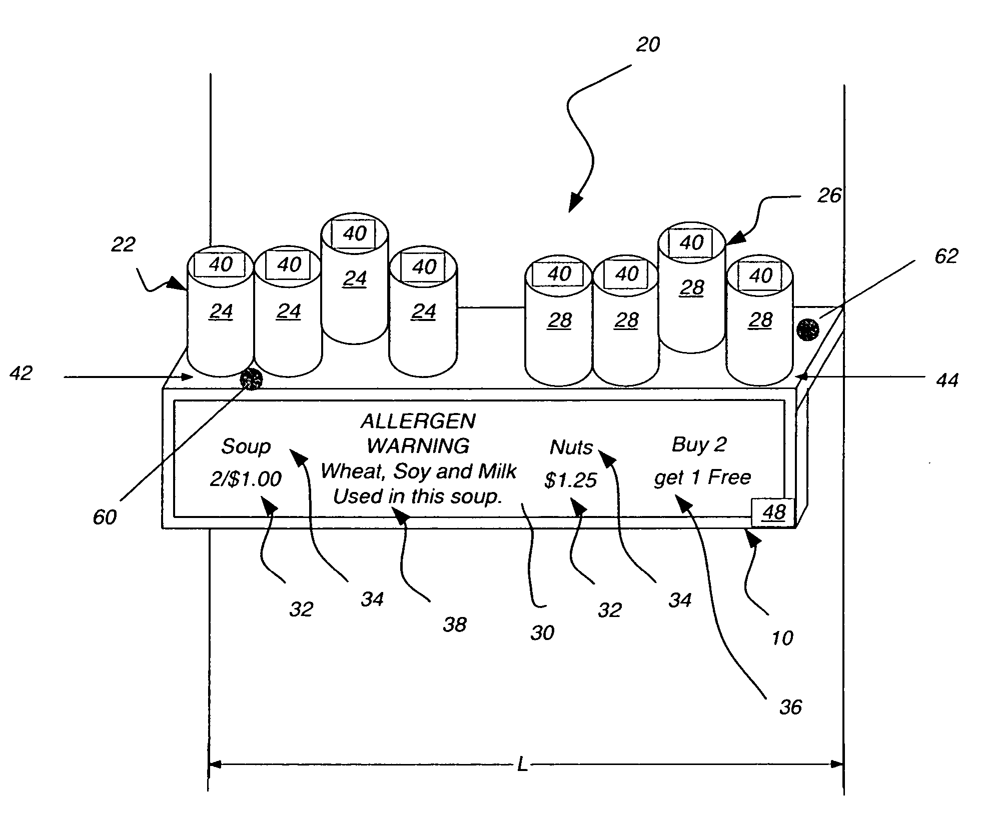
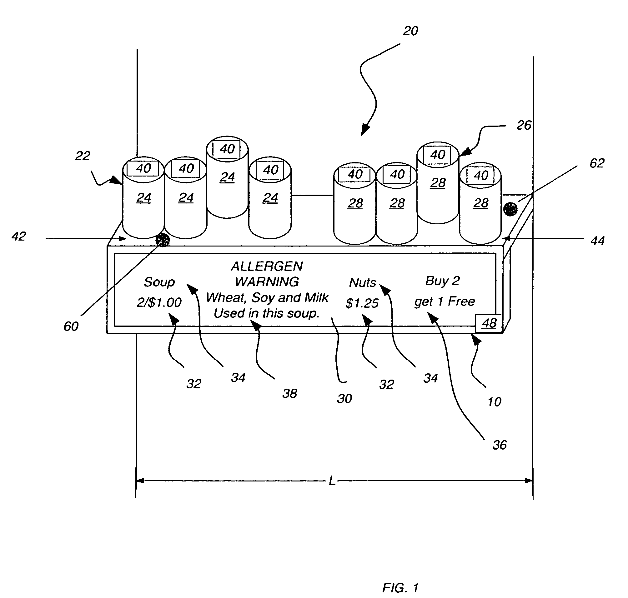
[0023]FIG. 1 shows a first embodiment of an electronic product identifier system 10 of the invention that is adapted for use with a product storage area 20 adapted to store a supply of more than one type of product arranged along a length L of storage area 20 of a type used in a storage facility 21, such as a retail store, a warehouse, a pharmacy or any other storage structure. As shown, storage area 20 stores a supply 22 of a first product 24 and a supply 26 of a second product 28. In the embodiment of FIG. 1, electronic product identifier system 10 has a display 30 that has a length that extends along length L of storage area 20 and that is adapted to present product information for more than one product along the length L of storage area 20. Storage area 20 can be a horizontal shelf 29 as illustrated in FIG. 1, an end-cap kiosk, a pegboard, a clothing rack or any other device configured to store products. In the embodiment shown in FIG. 1, which illustrates storage area 20 as hav...


PUM


Abstract

An electronic product identifier system is provided for use with a product storage area adapted to store more than one type of product. The electronic product identifier system has a display adapted to present product information for more than one product along a length of the storage area. Each product has an electronic product identifier. An electromagnetic sensing circuit is provided having at least one transmitter for transmitting polling electromagnetic fields so that the electronic product identifier associated with each product can generate a response. The electromagnetic sensing circuit further has at least one receiver for receiving each responsive electromagnetic signal at two separated sensing locations. A location circuit determines a location of each responsive electronic product identifier using the electromagnetic signals received; a data interface determines product information for each product type; and a display controller causes product information to be presented proximate to products of that type.

Description

CROSS REFERENCE TO RELATED APPLICATIONS[0001]This application is related to U.S. Ser. No. 11 / 191,647, entitled AUTOMATIC PLAN-O-GRAM SYSTEM in the names of Smith et al. filed concurrently herewith.FIELD OF THE INVENTION[0002]The invention relates to the field of electronic displays of the type for use in on storage shelves and other storage areas.BACKGROUND OF THE INVENTION[0003]Electronic shelf labels in retail store environments are well known in the art. One major disadvantage of prior systems is that they need some form of manual intervention to ensure that the electronic shelf labels are positioned at the appropriate places on the shelves. Thus, when the items on the shelf are moved for one of several reasons, e.g. store resets, promotional placement, the addition or removal of items, or seasonal changes, then there becomes a need to reconfigure the arrangement of electronic shelf labels on the shelf to exchange the electronic shelf labels to represent the required information....

Claims


Application Information

Patent Timeline
Patent Type & Authority Patents(United States)
IPC IPC(8): G06K7/08G05B19/00G06F19/00G08B21/00G06Q30/00G06K15/00
CPCG06Q10/087
Inventor SMITH, PHILIP J.ELLINGER, CAROLYN R.SCHINDLER, II, ROLAND R.
Owner IRIS OPTRONICS CO LTD
Why Eureka
Try Eureka