Lock mechanism and latch device

a latch device and lock mechanism technology, applied in the direction of coupling device connection, carpet fastener, mechanical apparatus, etc., can solve the problems of trace member twisting and poor durability, and achieve the effect of reducing mold expense, improving durability, and high measurement precision

Active Publication Date: 2008-07-01
NIFCO INC
View PDF6 Cites 58 Cited by
  • Summary
  • Abstract
  • Description
  • Claims
  • Application Information

AI Technical Summary

Benefits of technology

[0012]Because it is not the case that the trace part is made to circulate by causing twisting force on the trace member, there is no requirement for high measurement precision in the circulating cam groove, and the mold expense can be reduced. Also, because twisting force is not caused on the trace member, the durability of the trace member can be improved.
[0031]Because the present invention is made of the above constitution, when the one trace part of the trace member circulates following the circulating cam groove, the other trace part does not contact the wall surface, and therefore there is no occurrence of twisting force on the trace member, there is no requirement for high measurement precision in the circulating cam groove, and the mold expense can be reduced. Also, because twisting force is not caused on the trace member, the durability of the trace member can be improved. Furthermore, because only roughly the same sliding resistance as in the case when only one trace part is used is caused, regardless of the fact that two trace parts are being used, smooth operation can be obtained. Also, because the locked state of the moving member can be held by two trace parts, the lock strength can be improved compared with the case when the locked state is held by one trace part.

Problems solved by technology

These trace parts are pushed by the groove wall surface of the circulating cam groove in each pushing-in operation of the latch body, but because the shapes of the circulating cam grooves differ between the front side and the back side of the latch body, twisting is caused in the trace member.
However, in Japanese Patent No. 3126992, because the trace parts are made to circulate by twisting force on the trace member, the durability of the trace member is not good.

Method used


Image

  • Lock mechanism and latch device
  • Lock mechanism and latch device
  • Lock mechanism and latch device

Examples


Embodiment Construction

[0044]A latch device pertaining to a mode of working of the present invention is now explained.

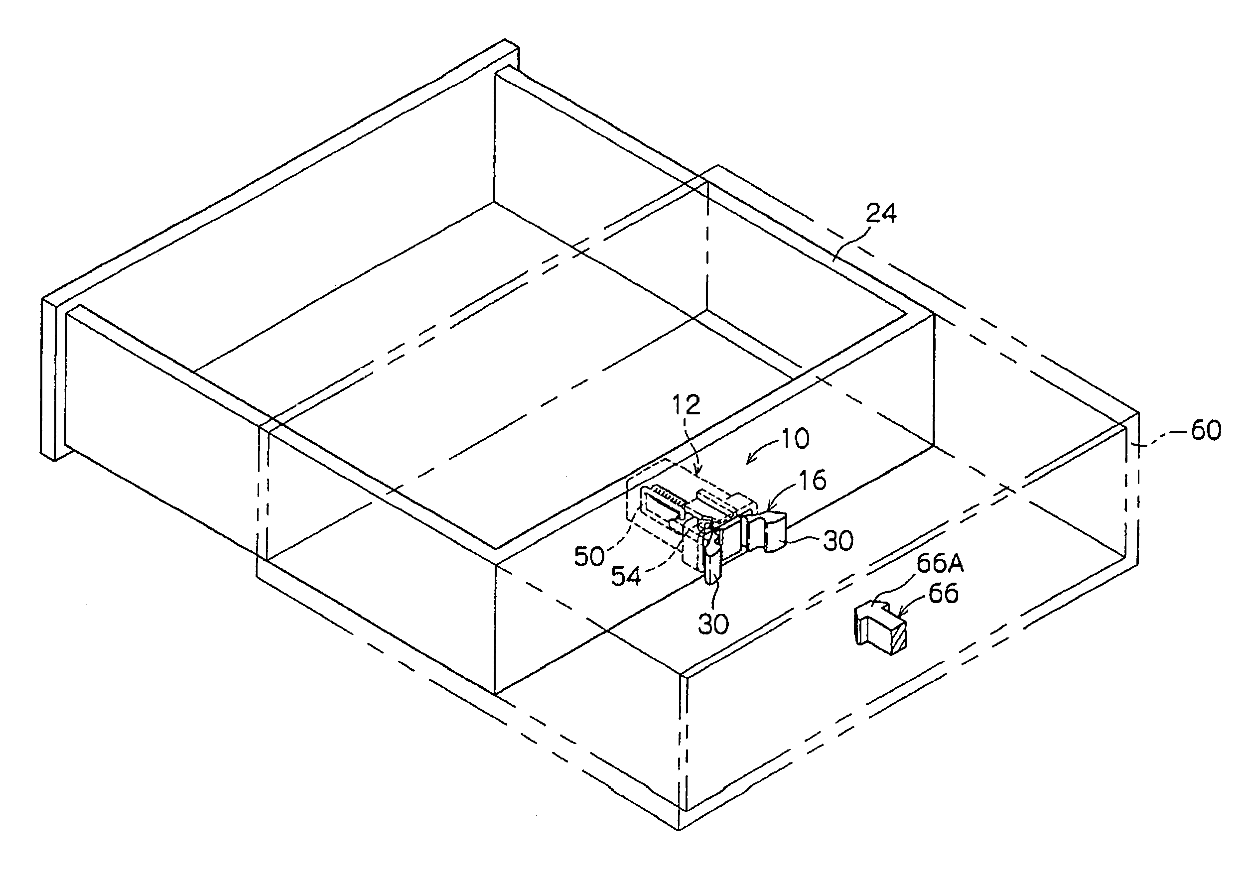
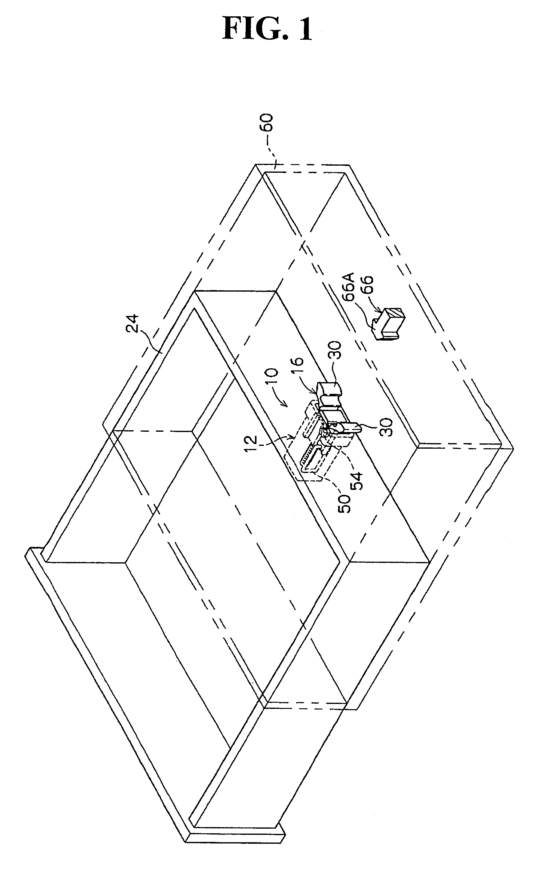
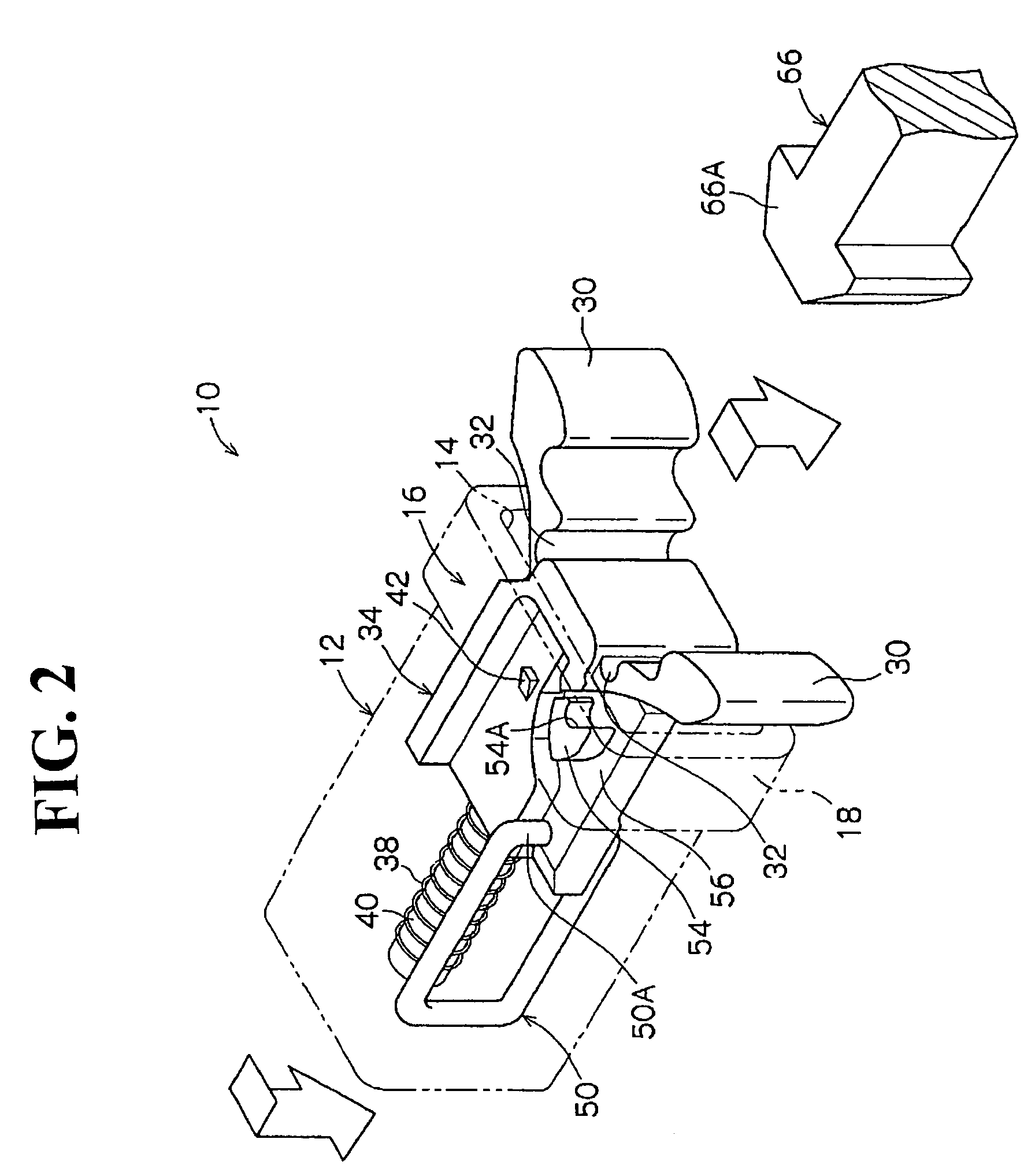
[0045]As shown in FIG. 1 through FIGS. 4(A) and (B), the latch device 10 has a box-shaped housing 12, and an opening 14 is formed on one end in the lengthwise direction. The latch body 16 is made capable of being housed inside this housing 12, and the latch body 16 is inserted from the opening 14.

[0046]A gripping piece 30 sticking outward is provided on the front end part of the latch body 16, and a hinge part 32 is provided on the base part of the gripping piece 30 so that it is made capable of elastic deformation. By this, the gripping piece 30 becomes capable of approaching and moving away from itself.

[0047]Also, the base part 34 of the latch body 16 is roughly parallelepiped-shaped, and in FIG. 4(A), a circular hole 36 is formed on the left side of the base part 34 following the lengthwise direction from the bottom surface of the base part 34. A compression coil spring 38 is made capab...


PUM


Abstract

A lock mechanism holds a moving member on a main body immovably in a locked state and allows movement in an unlocked state. The lock mechanism includes a circulating cam groove formed on the main body or the moving member, and a trace member having an angle bracket shape with one and the other trace parts to sway on the main body or moving member. The one trace part circulates along the circulating cam groove in each approaching and moving away operation of the moving member, and locks the moving member in a state having coupled with the coupling part. A wall surface is formed on the main body or moving member to be disposed in a different position from the circulating cam groove so that the other trace part of the trace member is operable to contact the wall surface only in the locked state of the moving member.

Description

BACKGROUND OF THE INVENTION AND RELATED-ART STATEMENT[0001]The present invention relates to a lock mechanism, and a latch device, which has a moving member that is capable of approaching and moving away from a main body, and holds said moving member to be immovable in the locked position and enables movement in the unlocked state.[0002]In vehicle compartment internal accessories such as cup holders and ashtrays, and audio devices., and the like, some have latch devices in order to close an opening-and-closing lid. For example, in Japanese Patent No. 3126992, a pair of circulating cam grooves having mutually different shapes is formed on both sides of a latch body 16. Also, the base part of a trace member is fixed on a housing, and a pair of trace parts formed on a trace part of the trace member is made capable of tracing respectively following the pair of circulating cam grooves.[0003]These trace parts are pushed by the groove wall surface of the circulating cam groove in each pushi...

Claims


Application Information

Patent Timeline
Patent Type & Authority Patents(United States)
IPC IPC(8): E05B15/02
CPCH01R13/62905H01R13/627E05B65/46E05C19/02Y10S292/04Y10T292/696
Inventor IKEDA, YASUHIKOUEKI, YASUSHITOMITA, SHIGEMITSU
Owner NIFCO INC
Why Eureka
Try Eureka