
Bracketless magnetic pump

a magnetic pump and bracketless technology, applied in the direction of machines/engines, liquid fuel engines, positive displacement liquid engines, etc., can solve the problems of unsatisfactory prior designs and add unwanted heat to the aquarium, and achieve the effect of low physical volume and high magnetic flux

Active Publication Date: 2008-07-01
ECOTECH
View PDF19 Cites 77 Cited by
  • Summary
  • Abstract
  • Description
  • Claims
  • Application Information

AI Technical Summary

Benefits of technology

"The present invention provides a fluid pump assembly for use in a fluid container. The assembly includes a first magnetic assembly and a second magnetic assembly, both operatively associated with a drive motor, and a non-magnetic spacer separating the two magnetic assemblies. The drive motor and the propeller are magnetically coupled to each other through the spacer for drivingly coupling them. The assembly also includes a first casing and a second casing, which are detachably held together solely by magnetic attraction force between the magnetic assemblies. The invention further includes a method of circulating water within an aquarium by positioning the first and second casings on the exterior and interior walls of the container, respectively, and using magnetic attraction to keep them aligned. The technical effects of the invention include improved fluid pumping efficiency, simplified assembly and disassembly, and improved alignment accuracy for magnetic coupling."

Problems solved by technology

First, designs featuring epoxy sealed motors within the aquarium have the unfortunate side effect of being relatively large and distracting to the intrinsic beauty of an aquarium, add unwanted heat to the aquarium through direct contact with the motor stator, and require that electricity be brought into the aquarium itself via a power chord or a battery sealed into the motor assembly.
Second, some prior designs utilize a mechanical bracket which hangs over the top of the aquarium in order to support the pump within the aquarium.
The prior designs are unsatisfactory because they are bulky due to the motor being placed within the aquarium or due to the brackets supporting the motor outside the aquarium.

Method used


Image

  • Bracketless magnetic pump
  • Bracketless magnetic pump
  • Bracketless magnetic pump

Examples


Embodiment Construction

)

[0020]The preferred embodiments of the present invention will now be described with the reference to accompanying drawings.

[0021]For purposes of the following description, certain terminology is used in the following description for convenience only and is not limiting. The words such as “inside”, “outside”, “top”, “bottom” and “side” designate directions in the drawings to which reference is made. The words “smaller” and “larger” refer to relative size of elements of the apparatus of the present invention and designated portions thereof. The terminology includes the words specifically mentioned above, derivatives thereof and words of similar import. Additionally, the word “a”, as used in the claims, means “at least one”.

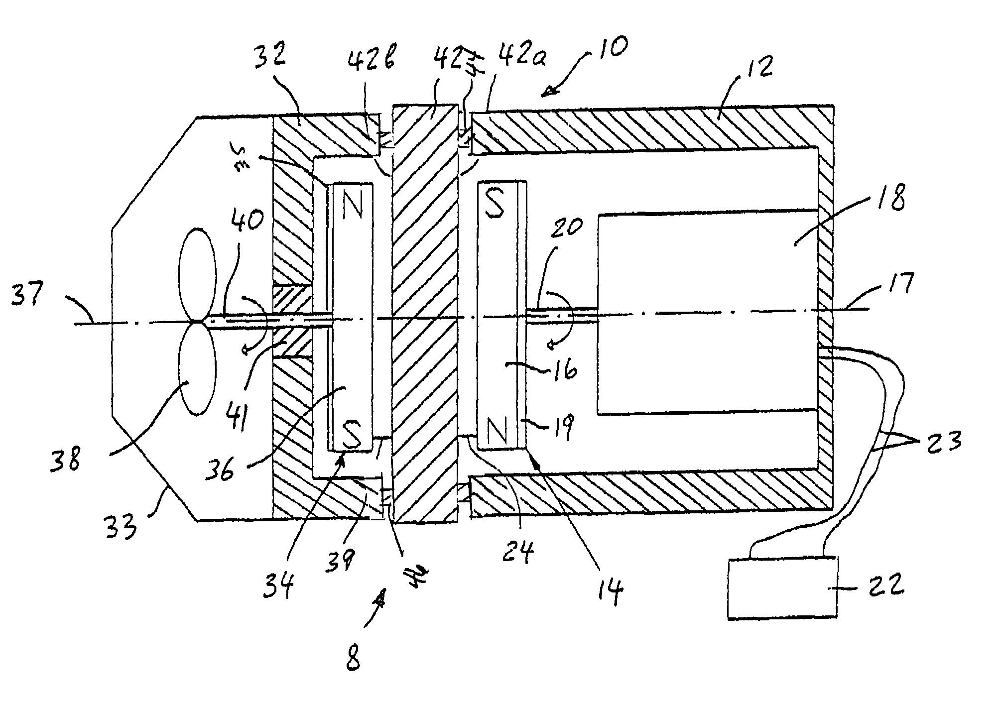
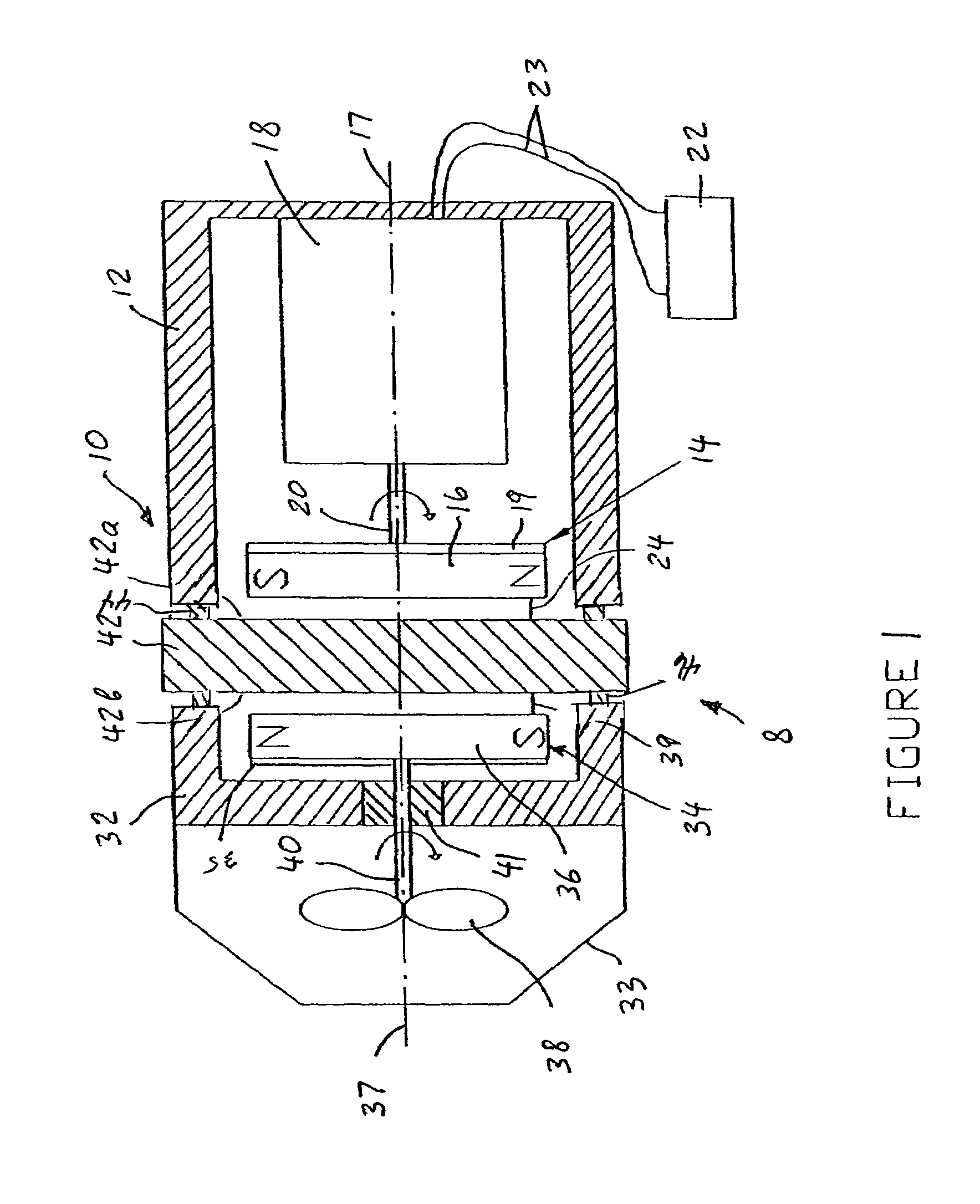
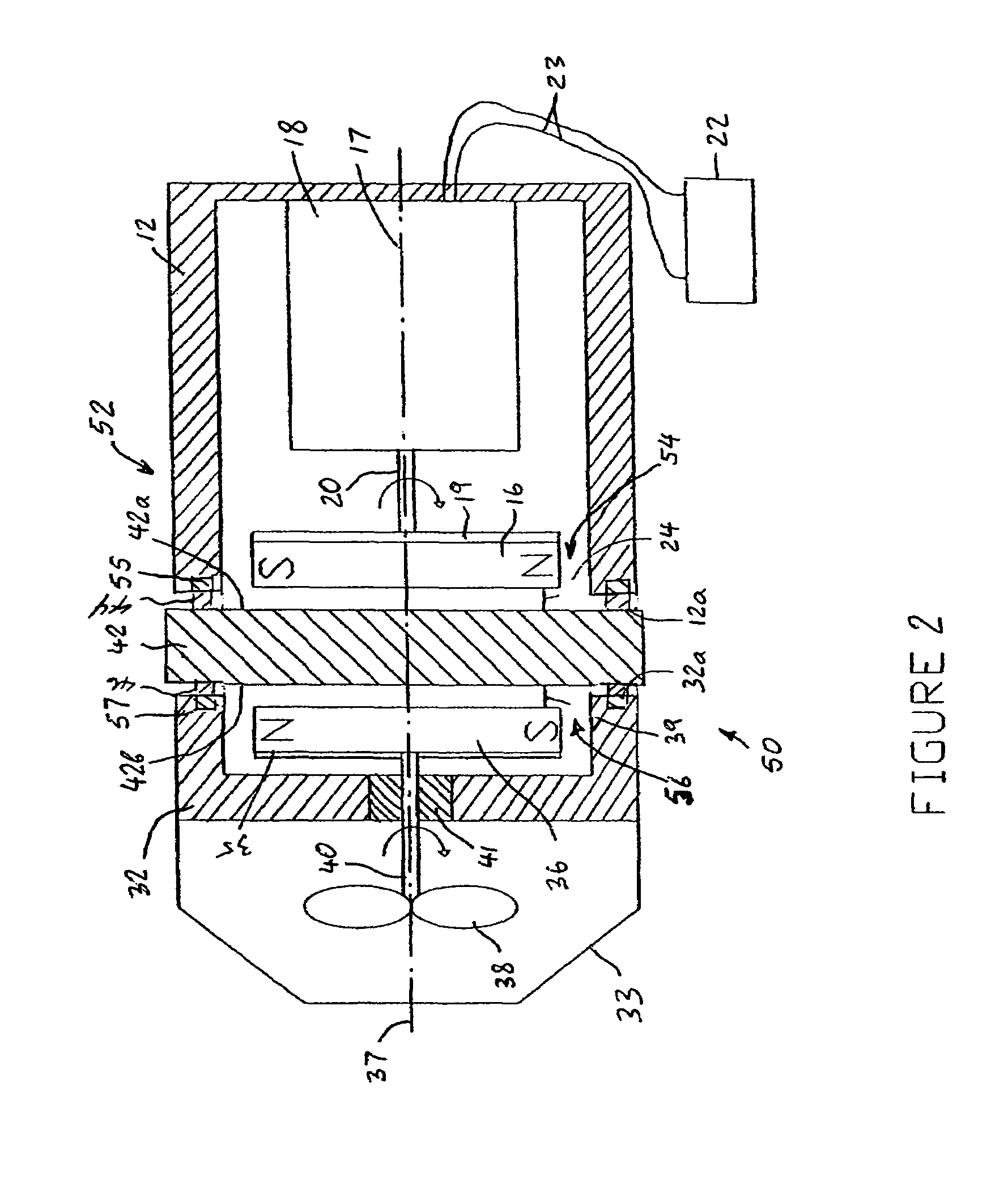
[0022]FIG. 1 depicts a fluid pump kit 8 comprising a fluid pump assembly according to a first exemplary embodiment of the present invention, generally depicted with the reference numeral 10, in the form of a kit. The fluid pump assembly 10 comprises a first casing ...


PUM

PropertyMeasurementUnit
thicknessaaaaaaaaaa
magnetic assembliesaaaaaaaaaa
magnetic attraction forceaaaaaaaaaa

Abstract

A fluid pump assembly is used in combination with a container having a wall. The pump assembly comprises a first casing disposed outside the container in contact with the wall, a first magnetic assembly mounted to the first casing and operatively associated with a drive motor, a second casing disposed inside the container in contact with the wall, and a second magnetic assembly mounted to the second casing and operatively associated with an propeller. The first magnetic assembly includes a rotatable magnetic drive member drivingly coupled to the drive motor. The magnetic drive member is magnetically coupled to the magnetic driven member through the wall for imparting a rotary driving force of the drive motor to the propeller. Furthermore, the second casing is detachably connected to the second side of the wall of the container solely by magnetic attraction force between the first and second magnetic assemblies.

Description

CROSS-REFERENCE TO RELATED APPLICATIONS AND CLAIM TO PRIORITY[0001]This application is related to provisional patent application No. 60 / 662,771, filed Mar. 16, 2005, the disclosure of which is incorporated by reference and to which priority is claimed.FIELD OF THE INVENTION[0002]The present invention relates to fluid pump assemblies in general, and more particularly to a fluid pump that is magnetically supported in position and in which a driving force is transmitted to an propeller through the medium of magnetic force.BACKGROUND OF THE INVENTION[0003]In order to properly care for fish and other aquatic organisms contained within a reef aquarium, adequate circulation is required. The role of circulation is two fold: first, circulation acts to constantly mix the aquarium water itself, ensuring that proper chemistry is maintained throughout the entire aquarium. Adequate circulation maintains the equilibrium of oxygen and carbon dioxide by increasing the rate at which water flows from ...

Claims


Application Information

Patent Timeline
Patent Type & Authority Patents(United States)
IPC IPC(8): F04B17/00A47K3/00
CPCF04D29/628F04D25/026F04D13/027Y10T29/49236A01K63/047F04D13/024F04D13/08F04D29/406F04D13/06F04D29/605
Inventor LAWYER, JUSTINCLASEN, PATRICKMARKS, TIMOTHY
Owner ECOTECH
Learn More