Current-mode control for switched step up-step down regulators
a regulator and step down technology, applied in the direction of dc-dc conversion, power conversion systems, instruments, etc., can solve the problems of difficulty in compensating for boost and buck-boom mode closed loop operation, and achieve the effect of short transition times and saving power
- Summary
- Abstract
- Description
- Claims
- Application Information
AI Technical Summary
Benefits of technology
Problems solved by technology
Method used
Image
Examples
Embodiment Construction
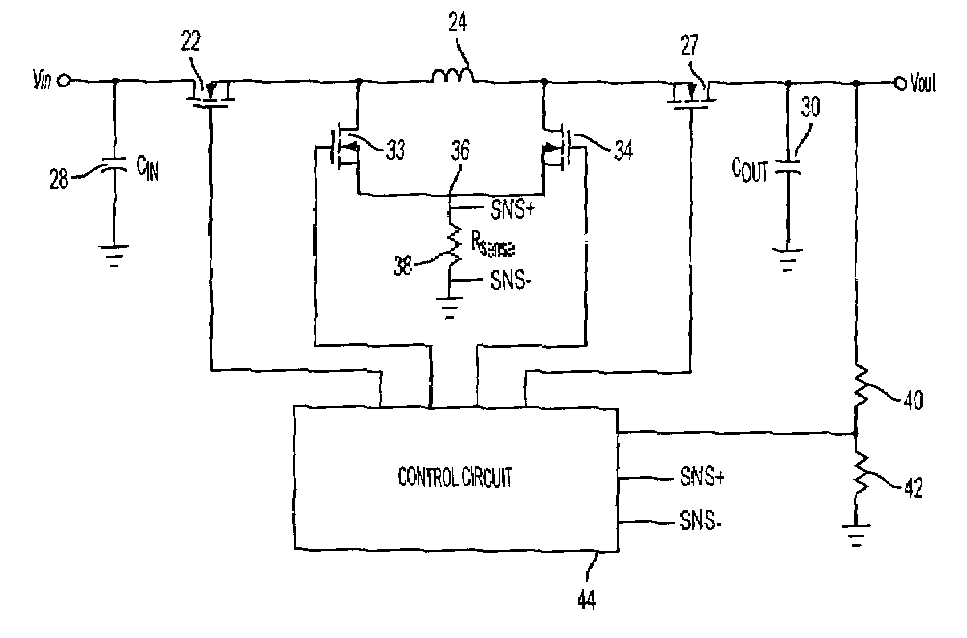
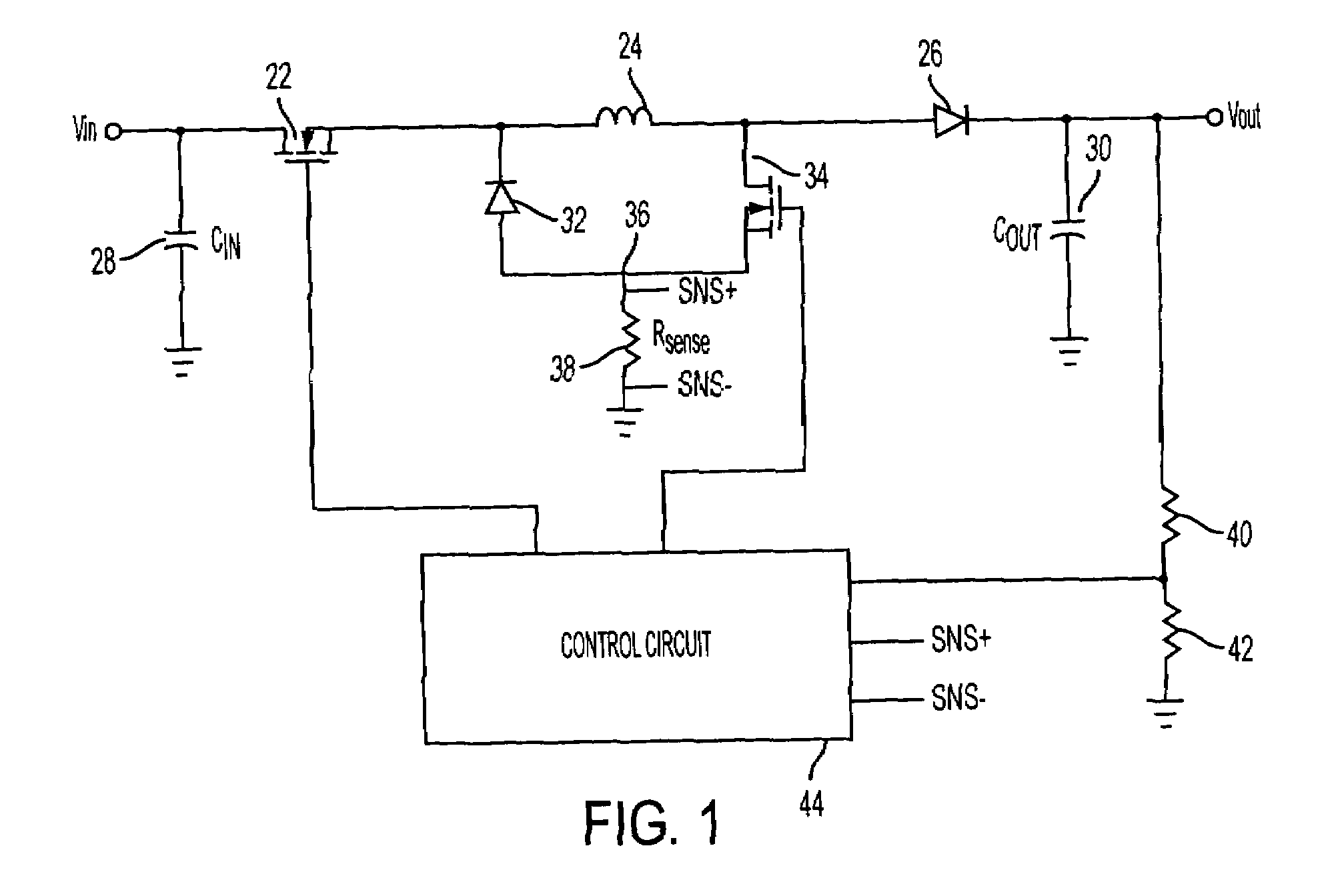
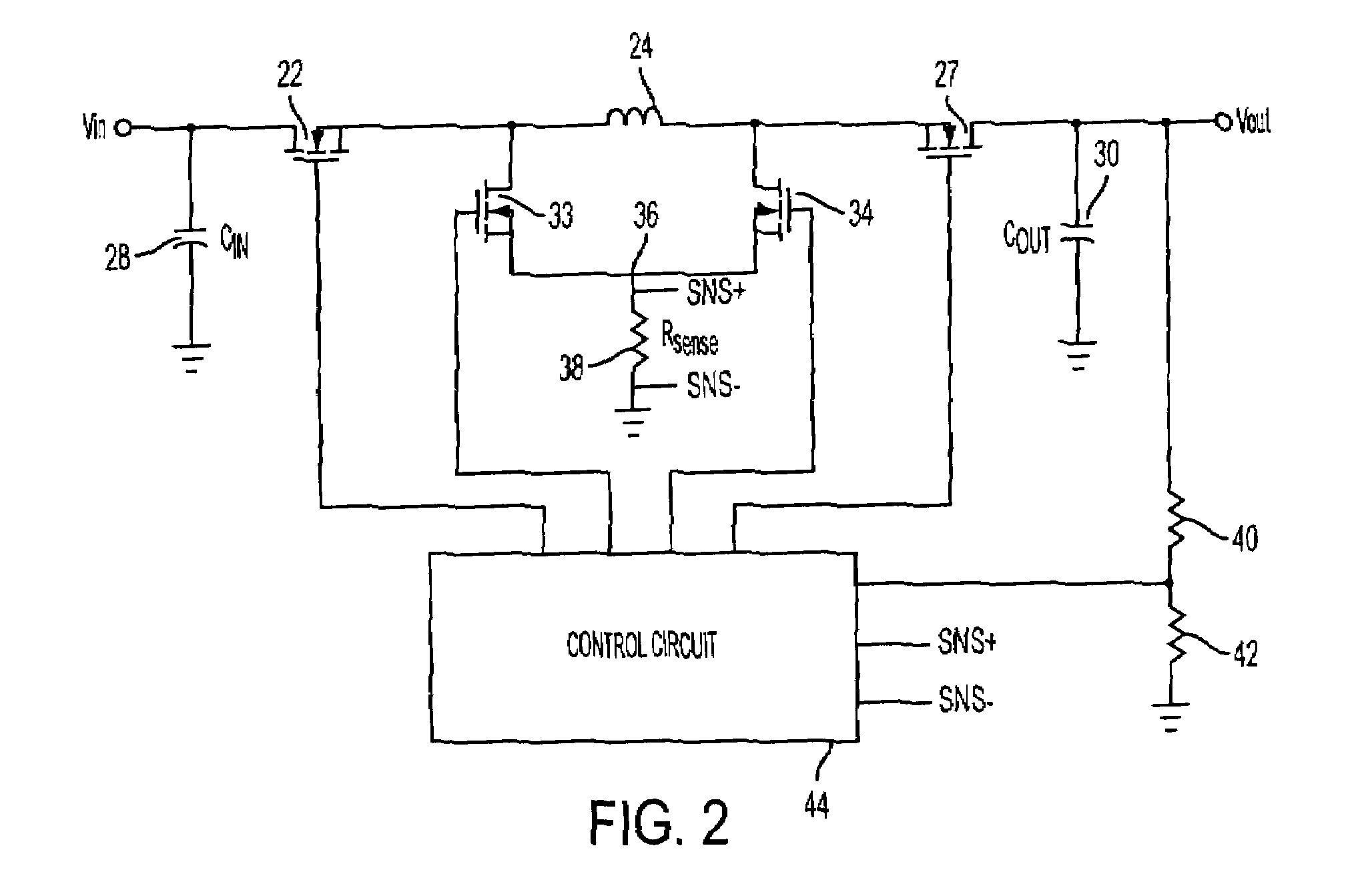
[0030]A switching regulator is represented in the schematic block diagram of FIG. 1. An input voltage from a power supply is applied to input terminal Vin. A preset output voltage is regulated at the Vout terminal. Connected in series between the input and output terminals are a first switch 22, inductor 24, and rectifier 26. Rectifier 26 is connected to conduct current in the direction of the output terminal. Switch 22 preferably is a MOSFET, although any controlled switching device may be utilized.
[0031]An input capacitor 28 is connected between the input terminal and the common ground. An output capacitor 30 is connected between the output terminal and the common ground. Rectifier 32 and a second switch 34 are connected across inductor 24 and joined at node 36. Rectifier 32 is connected to conduct current in the direction of the inductor 24. Current sense resistor 38 is connected between node 36 and the common ground. Voltage divider resistors 40 and 42 are connected in series be...
PUM
 Abstract
Description
Claims
Application Information
 - R&D
- Intellectual Property
- Life Sciences
- Materials
- Tech Scout
- Unparalleled Data Quality
- Higher Quality Content
- 60% Fewer Hallucinations
Browse by: Latest US Patents, China's latest patents, Technical Efficacy Thesaurus, Application Domain, Technology Topic, Popular Technical Reports.
© 2025 PatSnap. All rights reserved.Legal|Privacy policy|Modern Slavery Act Transparency Statement|Sitemap|About US| Contact US: help@patsnap.com


