
Bi-directional universal serial bus booster circuit

a booster circuit and serial bus technology, applied in the field of booster circuits, can solve the problems of signal failure, adversely affecting signal quality, and increasing bus length,

Inactive Publication Date: 2008-07-01
IBM CORP
View PDF8 Cites 24 Cited by
  • Summary
  • Abstract
  • Description
  • Claims
  • Application Information

AI Technical Summary

Problems solved by technology

However, as the number of connected devices increases, the length of the bus also increases which in turn adversely impacts signal quality.
If a signal on the bus falls outside of the eye diagram specified by the USB standard, the signal will fail.
A device that is normally USB compliant, meaning it transmits signals that comply with the standard, may start to fail if too many devices are coupled to the same bus, or if the physical length of the bus becomes too long.
Thus, the number of devices and the speed of data transfer are limited by the quality of the signal.

Method used


Image

  • Bi-directional universal serial bus booster circuit
  • Bi-directional universal serial bus booster circuit
  • Bi-directional universal serial bus booster circuit

Examples


Embodiment Construction

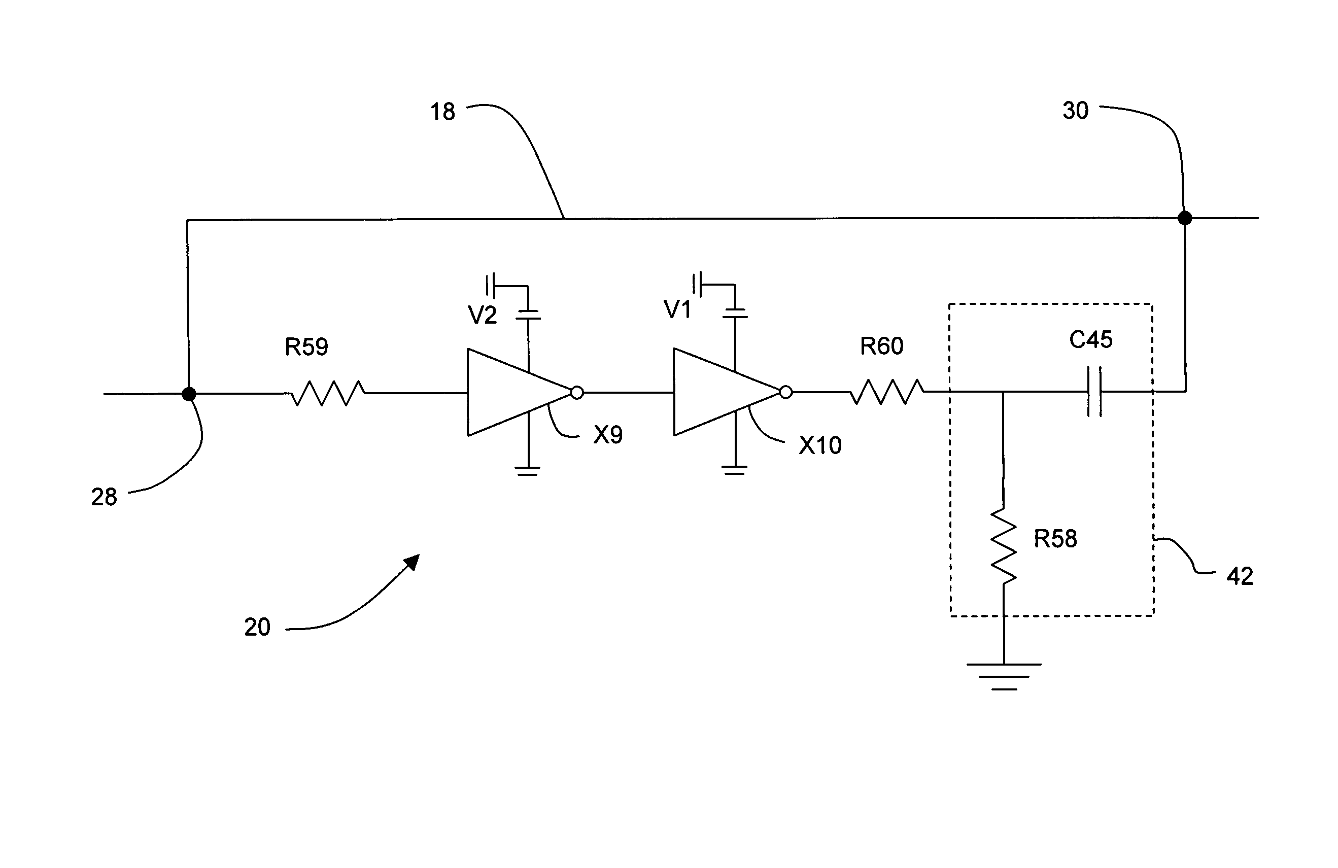
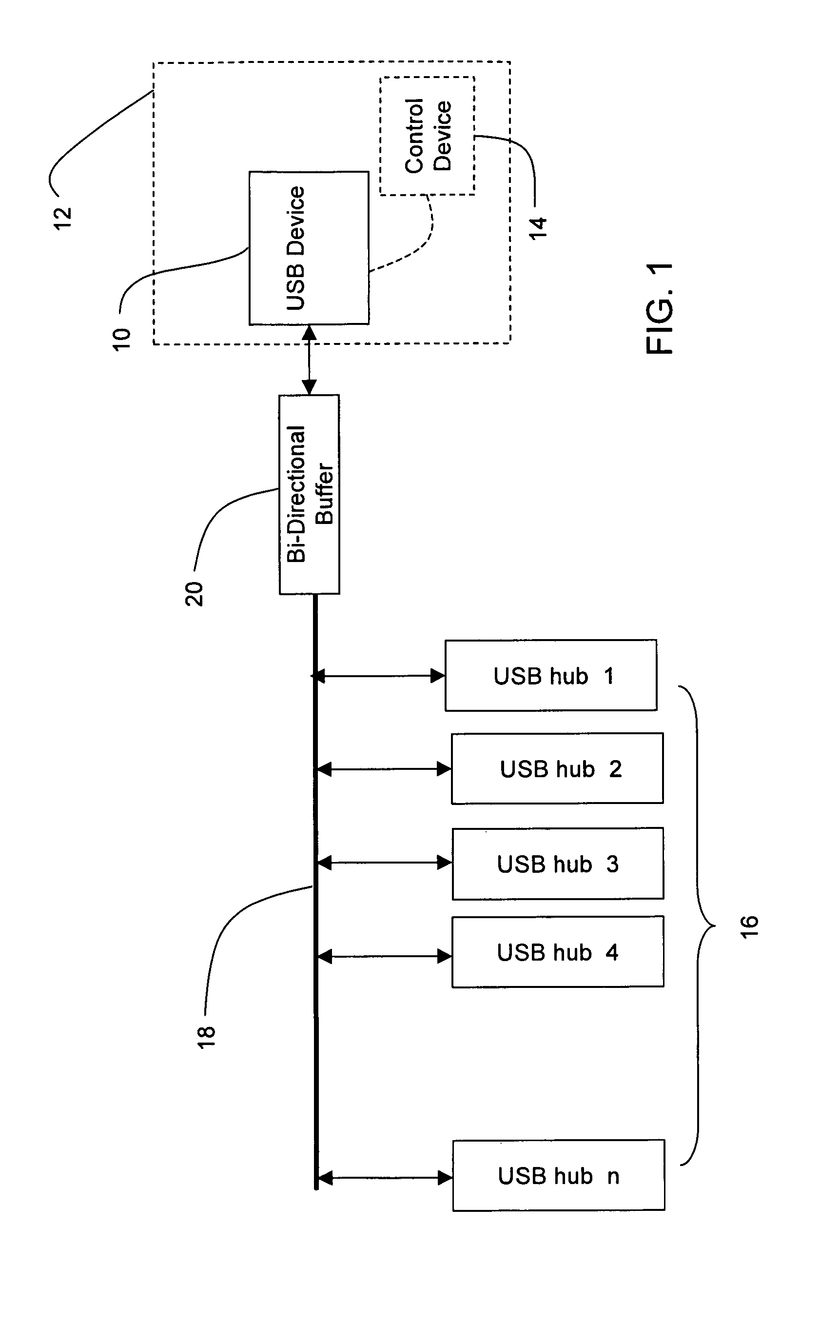
[0016]A system incorporating a universal serial bus (“USB”) compliant bus is illustrated in FIG. 1. The USB root hub 10 may be root hub coupled to a computer 12 such as a BladeCenter® manufactured by International Business Machines Corporation. A root hub 10 is typically built into a host controller 14 that couples and translates the signals received over the USB bus with other circuitry in the computer 12. Alternatively, the USB device 10 may be a USB hub that couples downstream USB Hubs 16 to an upstream bus (not shown). The USB device 10 is coupled to the USB bus 18 by a bi-directional booster circuit 20. It should be appreciated that the USB standard allows for multiple tiers of USB devices, commonly called branches, to be coupled together and that the bi-directional booster circuit 20 described herein may be used with any or all of the tiers.

[0017]As it will be described in more detail herein, the bi-directional booster circuit 20 does not electrically isolate the components co...


PUM


Abstract

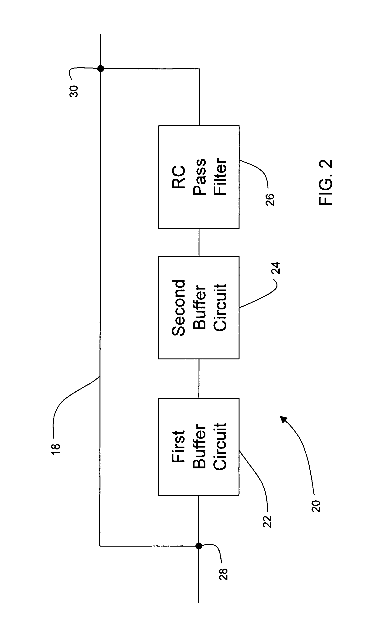
A bi-directional universal serial bus (“USB”) circuit for boosting a signal on a USB bus disclosed. The circuit includes a first stage inverting buffer coupled to a second stage inverting buffer to form a non-inverting buffer circuit. A high pass filter is coupled in series with the non-inverting buffer circuit to provide AC coupling to the USB bus and to allow fast signal edges through the circuit. The booster circuit is arranged to improve signal quality over a USB bus to allow additional USB devices and longer USB busses to be utilized.

Description

TRADEMARKS[0001]IBM® is a registered trademark of International Business Machines Corporation, Armonk, N.Y., U.S.A. Other names used herein may be registered trademarks, trademarks or product names of International Business Machines Corporation or other companies.BACKGROUND OF THE INVENTION[0002]This invention relates generally to a booster circuit for a universal serial bus (“USB”) and in particular to a circuit having a two stage buffer circuit coupled to the USB bus through a high pass resistor-capacitor filter.[0003]Peripherals and external devices are commonly connected to a computer system using some type of bus arrangement. Traditionally, the connection was made using either a serial connection using a protocol such as RS-485 or via a parallel port using a protocol such as IEEE 1284. As the number of devices that needed to be connected increased, a new serial bus standard, known as universal serial bus (“USB”), was developed to aid in the interconnectability of computers and ...

Claims


Application Information

Patent Timeline
IPC IPC(8): H03K17/16
CPCG06F13/4072
Inventor BANDHOLZ, JUSTIN P.CASES, MOISESHERMAN, BRADLEY D.MATOGLU, ERDEMMUTNURY, BHYRAV M.PAHEL, THOMAS D.PATEL, PRAVIN S.PHAM, NAM H.WEST, CHRISTOPHER C.
Owner IBM CORP
Learn More