
Plane lens sheet using light transmission rate difference

a technology of light transmission rate and lens sheet, which is applied in the field of plane lens sheet, can solve the problems of difficult cleaning, lusterless products employing lens sheet, and difficult to produce lustrous lens sheet, and achieve the effects of high lustrous vivid colors, better depth perception, and higher resolution

Inactive Publication Date: 2008-07-01
CHUNG HYUNIN
View PDF1 Cites 12 Cited by
  • Summary
  • Abstract
  • Description
  • Claims
  • Application Information

AI Technical Summary

Benefits of technology

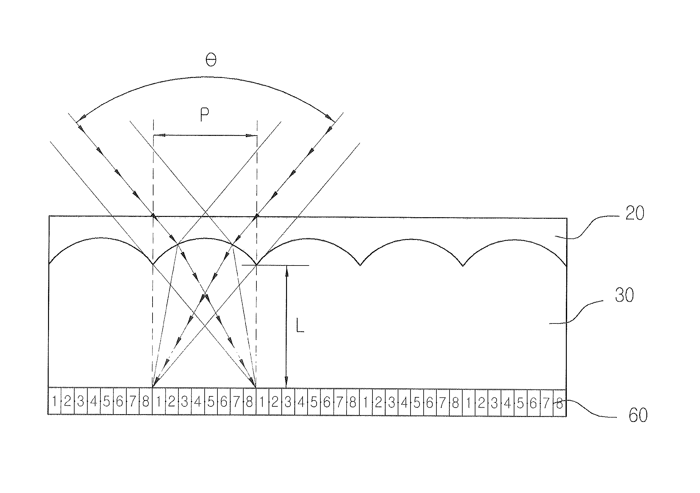
[0008]Accordingly, the present invention has been made in view of the above-mentioned problems occurring in the prior art, and it is a primary object of the present invention to provide a plane lens sheet using a light transmission rate difference, which has a perfectly plane surface to prevent foreign substances from being collected between lenses and remove surface diffused reflection generated in the lens sheet to reproduce highly lustrous vivid colors and gives a higher resolution and a better sense of depth as compared to the conventional stereoscopic printing lens sheet.

Problems solved by technology

However, the surface of the stereo lens sheet is embossed because of the lenses formed thereon, and thus there are many problems in manufacturing products employing the stereo lens sheet and managing the products.
That is, particles collect between embossed portions on the surface of the lens sheet and they are difficult to remove by cleaning.
Furthermore, the embossed surface of the lens sheet causes diffused reflection so that products employing the lens sheet look lusterless.
Thus it is difficult to produce a lustrous lens sheet.
Thus, the resolution of stereo graphic seems poor while the sense of depth seems improved when the stereo graphic is seen with the naked eye.

Method used


Image

  • Plane lens sheet using light transmission rate difference
  • Plane lens sheet using light transmission rate difference
  • Plane lens sheet using light transmission rate difference

Examples


Embodiment Construction

[0020]The present invention will now be described more fully with reference to the accompanying drawings, in which exemplary embodiments of the invention are shown.

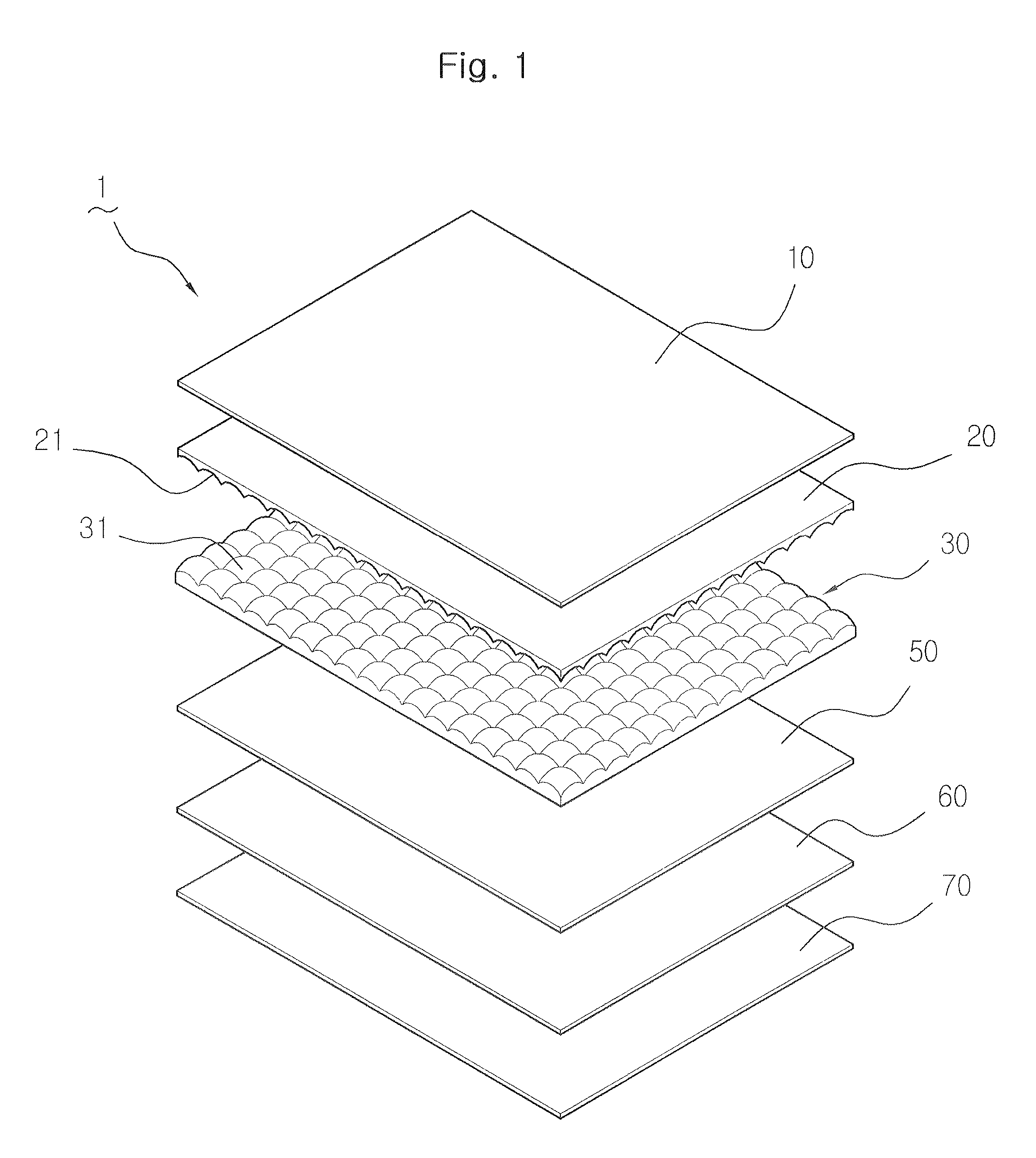
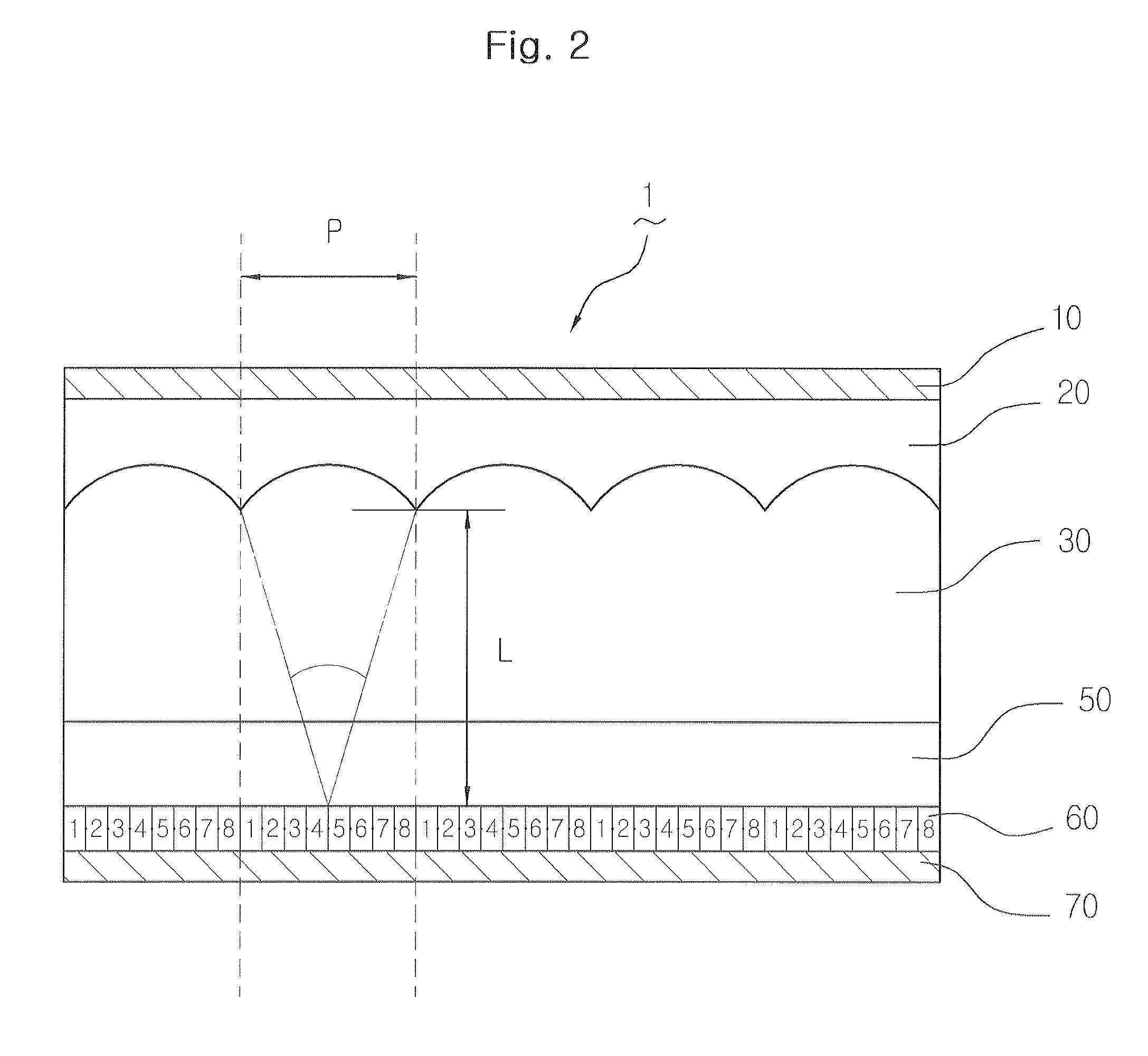
[0021]As shown in FIGS. 1 through 9, a plane lens sheet 1 according to the present invention includes a convex lens layer 30. The convex lens layer 30 is formed by molding a transparent synthetic resin into hemispherical convex lenses 31 arranged in every direction. The convex lenses 31 are arranged in such a manner that a cross angle of virtual lines passing the centers of the convex lenses 31 makes 60° or 90°.

[0022]A concave lens layer 20 is formed on the convex lens layer 30. The concave lens layer 20 is made of a transparent synthetic resin and has a light transmission rate different from that of the convex lens layer 30. The concave lens layer 20 includes concave lenses 21 that have the same radius of curvature as that of the convex lenses 31 and are arranged in the same manner as the convex lenses 31. The concave le...


PUM


Abstract

Disclosed herein is a plane lens sheet using a light transmission rate difference, which is used for stereoscopic printing for a lenticular system and an integral photography method and has a plane surface while innumerable lenses are arranged on the surface there so that it looks like a flat transparent sheet, improves the quality of stereoscopic products employing the lens sheet and facilitates the maintenance of the stereoscopic products. The plane lens sheet includes: a concave lens layer 20 and a convex lens layer 30 laminated on each other in such a manner as the adhere to each other with the same radius curvature to form a superposed lens sheet, the concave lens layer 20 and the convex lens layer 30 being made of a transparent synthetic resin and having the same lens pitch and different light transmission rates; a thin flat transparent upper protection layer 10 formed on the concave lens layer 20; a transparent layer 50 formed below the convex lens layer 30 for forming the focal length of the laminated concave lens layer and convex lens layer; and a thin flat transparent lower protection layer 70 formed below the transparent layer 50.

Description

BACKGROUND OF THE INVENTION[0001]1. Field of the Invention[0002]The present invention relates to a lane lens sheet using a light transmission rate difference, and more particularly, to a plane lens sheet using a light transmission rate difference, which is used for stereoscopic printing for a lenticular system and an integral photography method and has a plane surface while innumerable lenses are arranged on the surface thereof so that it looks like a flat transparent sheet, improves the quality of stereoscopic products employing the lens sheet and facilitates the maintenance of the stereoscopic products.[0003]2. Background of the Related Art[0004]Generally, a stereo lens sheet includes innumerable lenses formed in a pattern on its surface so that the surface looks embossed. The lenses of the stereo lens sheet are used to obtain refractive effect. However, the surface of the stereo lens sheet is embossed because of the lenses formed thereon, and thus there are many problems in manuf...

Claims


Application Information

Patent Timeline
IPC IPC(8): G02B27/10G03B21/60G02B3/00G02B3/06G03B35/00
CPCG03B35/24G02B27/2214B29D11/00G02B3/00G02B5/02G02B30/27
Inventor CHUNG, HYUNIN
Owner CHUNG HYUNIN
Learn More