
Dual range vehicle remote

a remote and dual-range technology, applied in the field of remote keyless entry systems, can solve the problems of inability to operate the same door unlock or trunk release function from the same two hundred meter distance, the type of method can be very unrepeatable, and the range is not always consistently and accurately determined

Inactive Publication Date: 2008-07-08
LEAR CORP
View PDF18 Cites 19 Cited by
  • Summary
  • Abstract
  • Description
  • Claims
  • Application Information

AI Technical Summary

Benefits of technology

[0009]An advantage of an embodiment of the present invention is that, for certain remote keyless entry functions where it is desirable to operate from a long distance, these functions may operate at these longer distances, while other short distance functions are disabled at such long distances. Thus, inadvertent actuation of short distance functions from a long distance can be avoided.
[0010]A further advantage of an embodiment of the present invention is that the ability to disable the short distance functions when the key fob is at a long distance may be performed in a consistent and repeatable manner.
[0011]An additional advantage of an embodiment of the present invention is that no received signal strength indicator (RSSI) or other distance calculating technology is required in the operation of this invention.

Problems solved by technology

Having the greater range of operation for the remote keyless entry system, however, may be undesirable for certain other remote keyless entry functions.
Moreover, one may not wish to inadvertently unlock the vehicle doors when at this longer range since one may be out of sight of the vehicle and thus not realize that the doors are unlocked.
Accordingly, it may be undesirable for door unlock or trunk release functions to be operable from the same two hundred meter distance.
But due to environmental conditions, such as ambient radio frequency noise, this type of method can be very unrepeatable—that is, the range is not always consistently and accurately determined.
Such inaccuracy may be undesirable for vehicle operators with these types of remote keyless entry systems.

Method used


Image

  • Dual range vehicle remote
  • Dual range vehicle remote
  • Dual range vehicle remote

Examples


Embodiment Construction

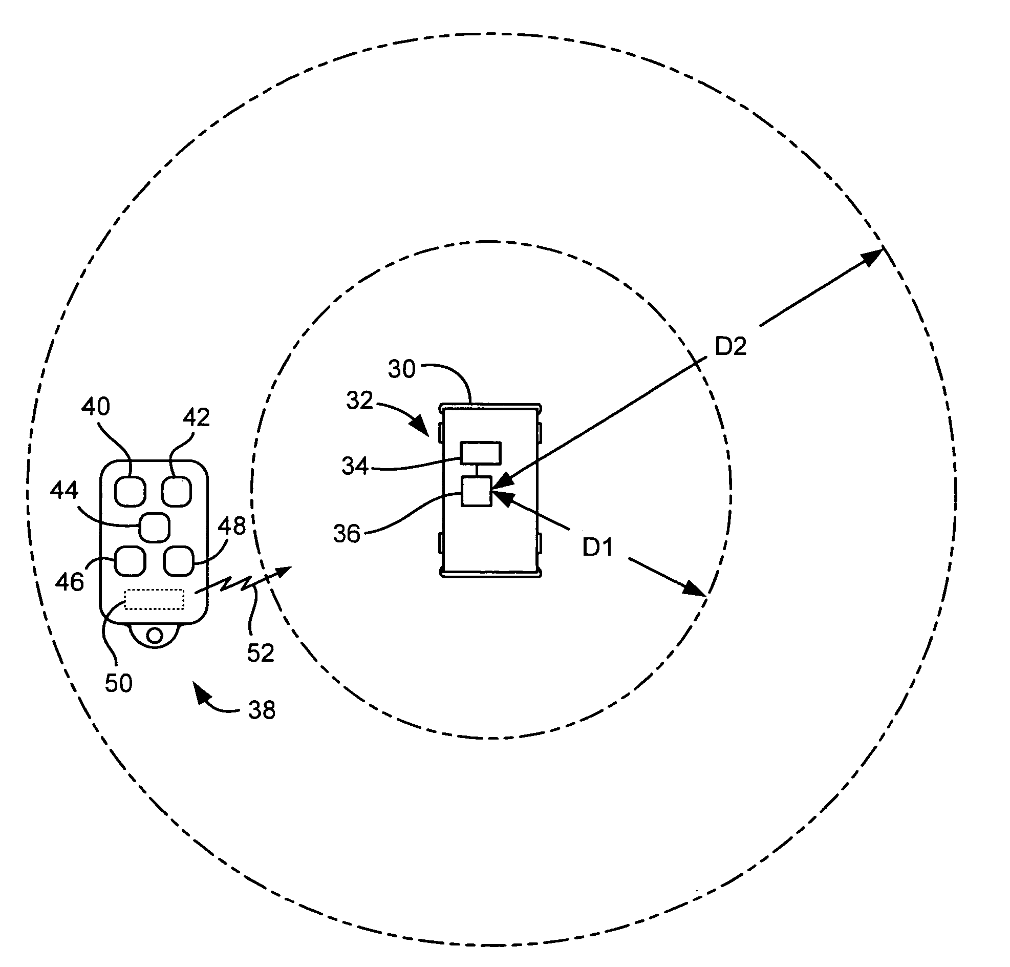
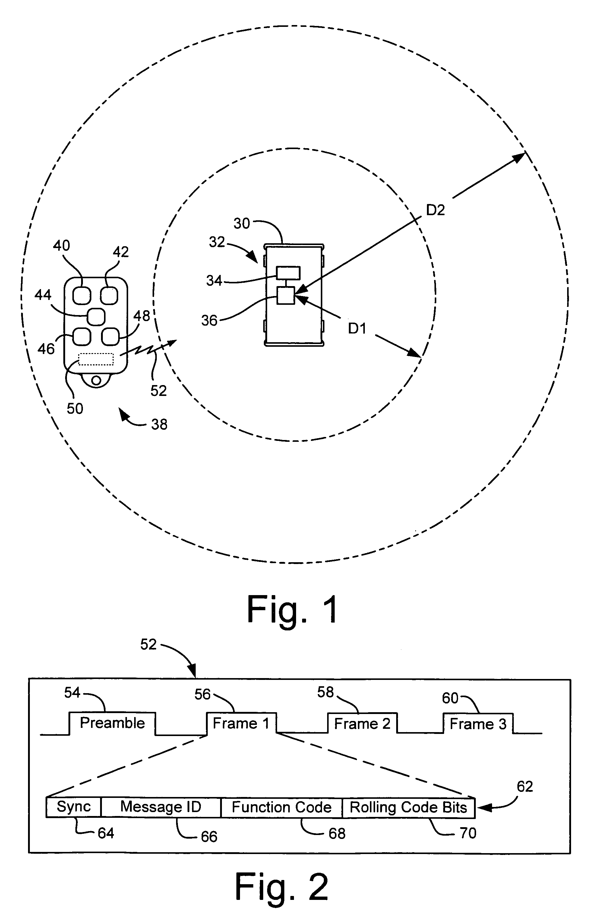
[0015]FIG. 1 schematically shows a vehicle 30 having a remote keyless entry system, indicated generally at 32. The remote keyless entry (RKE) system 32 includes a controller 34 in communication with a receiver 36. The controller 34 may be in communication with systems that carry out the desired RKE functions, such as a door lock / unlock actuator (not shown), a vehicle horn and headlights (not shown), an engine ignition system (not shown), and / or a trunk release mechanism (not shown). These systems will not be described in any detail since they are known to those skilled in the art. Moreover, the controller 34 and receiver 36 may be integral or separate components, and may be comprised of various combinations of hardware and software, as is known to those skilled in the art.

[0016]A key fob 38 includes a set of buttons, such as, for example, lock 40, unlock 42, engine start 44, alarm 46, and trunk release 48. Of course, additional or different remote functions may be performed by the k...


PUM


Abstract

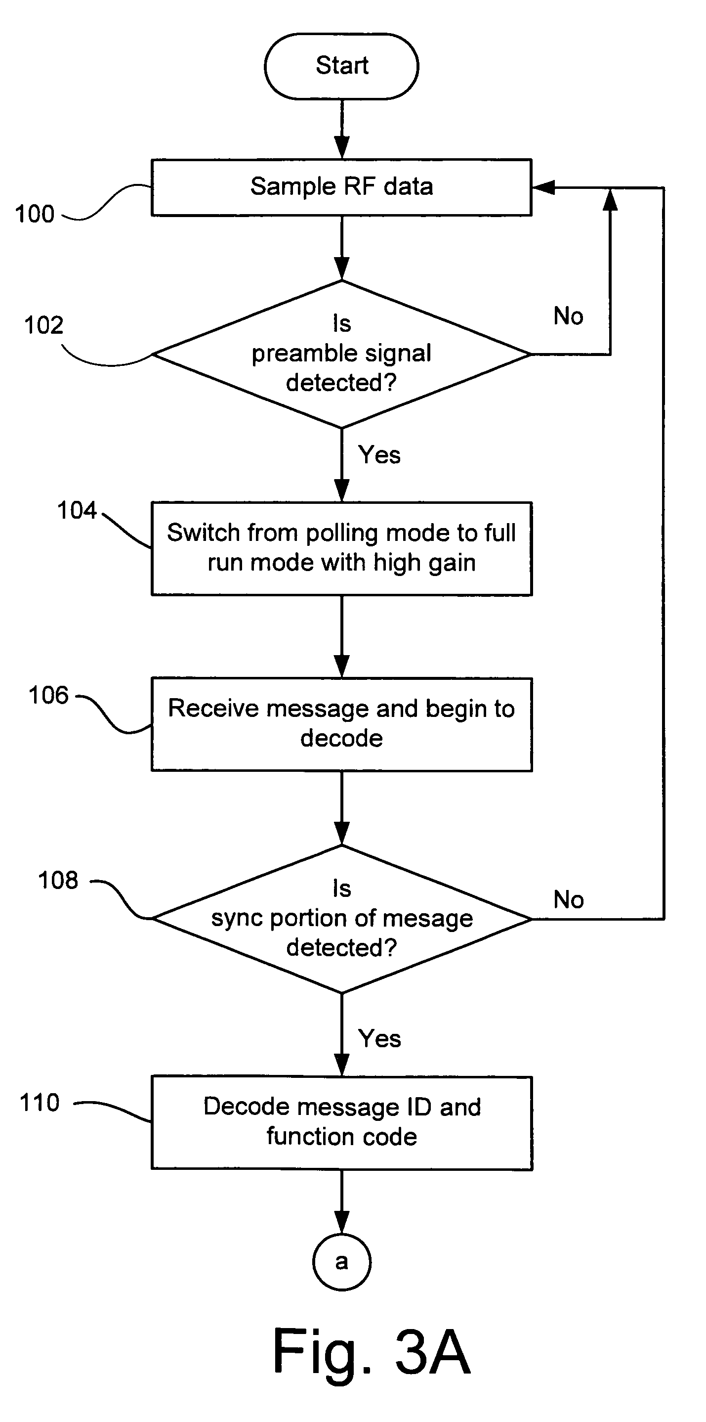
A method and system are disclosed for operating a controller of and a RKE system to provide for short distance functions that are actuatable from a key fob at a shorter distance from the vehicle than other long distance functions. This may include receiving a desired type of radio frequency signal; actuating a high gain mode of a receiver of the controller; detecting a message from an acceptable remote keyless entry transmitter; decoding a function code portion of the message; changing the receiver from the high gain mode to a lower gain mode if the function code is not a long distance function; decoding a remaining portion of the message; determining if the remaining portion of the message was decoded properly; and performing the requested function if the remaining portion of the message was decoded properly.

Description

BACKGROUND OF INVENTION[0001]The present invention relates to remote keyless entry types of systems employed with automotive vehicles.[0002]Remote keyless entry systems are commonly used with automotive vehicles today. Such systems are including a wider range of functions that can be performed by the remote keyless entry system. For example, not only are the conventional lock, unlock, trunk release, and panic functions available, but also new functions such as remote engine start.[0003]For certain functions, such as remote engine start, it is desirable to allow these functions to be performed while the operator is a greater distance from the vehicle than for some of the conventional functions. For example, one may wish to allow for the remote engine start, door lock, and panic alarm functions to be operable when the key fob is as far away from the vehicle as two hundred meters. To obtain this long rage functionality, the remote keyless entry system can be designed to operate at this...

Claims


Application Information

Patent Timeline
Patent Type & Authority Patents(United States)
IPC IPC(8): H04Q1/00G08C19/00
CPCB60R25/209B60R25/24G07C9/00174G07C2009/00261G07C9/00182B60R25/00
Inventor NANTZ, JOHNHONKANEN, MATTHEWCONNER, BRUCE D.
Owner LEAR CORP
Learn More