Voltage controlled oscillator delay cell and method

a delay cell and voltage control technology, applied in pulse manipulation, pulse technique, instruments, etc., can solve the problems of limited tuning range (range of frequencies at which a lock can occur) and limited range over which a pll can operate,

Active Publication Date: 2008-07-15
MONTEREY RES LLC
View PDF25 Cites 65 Cited by
  • Summary
  • Abstract
  • Description
  • Claims
  • Application Information

AI Technical Summary

Problems solved by technology

In such a case, a VCO response can limit the range over which a PLL can operate.
A drawback to conventional VCO delay cell 600 is that the tuning range (range of frequencies at which a lock can occur) can be limited unless post VCO voltage dividers are adjusted.
In particular, a lower frequency range may be limited.

Method used


Image

  • Voltage controlled oscillator delay cell and method
  • Voltage controlled oscillator delay cell and method
  • Voltage controlled oscillator delay cell and method

Examples


Embodiment Construction

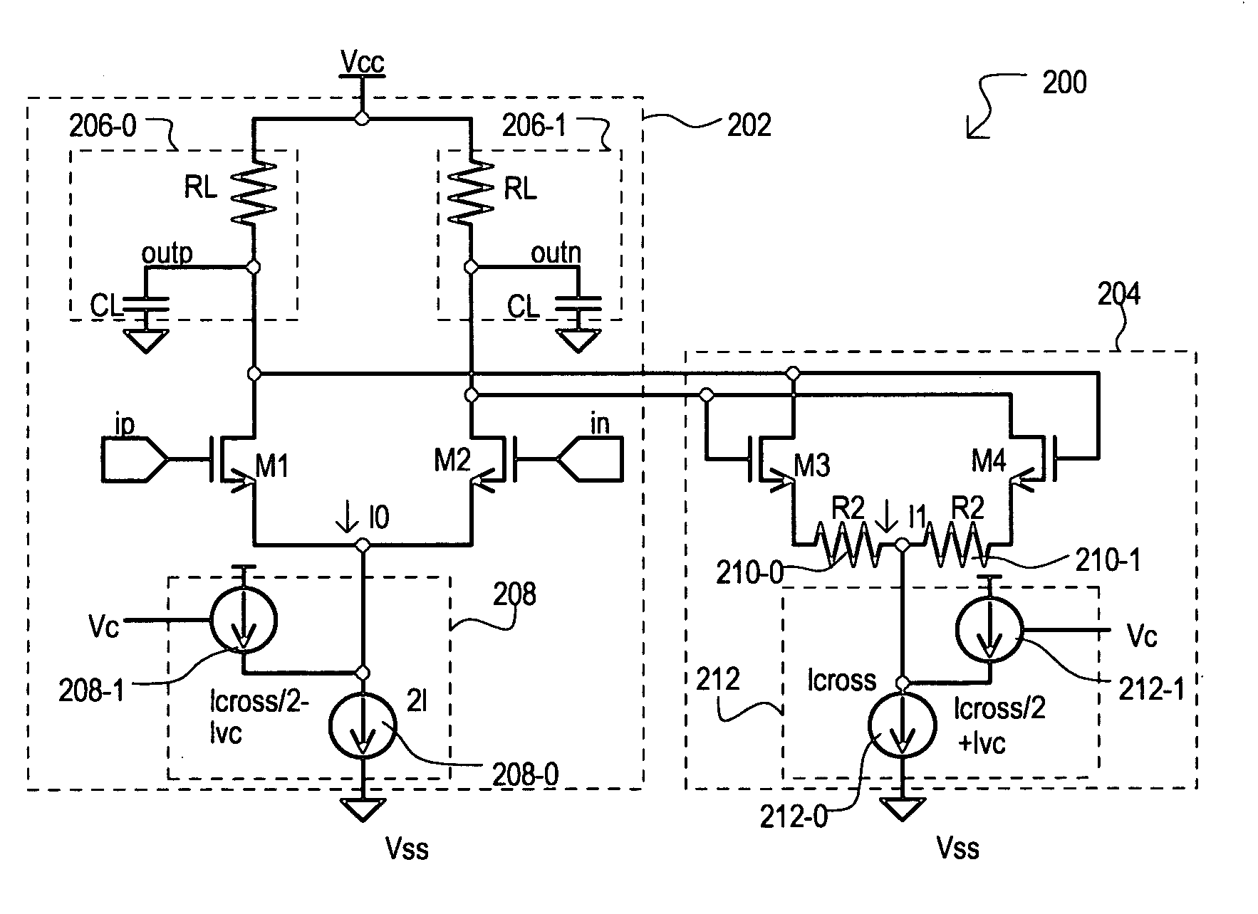
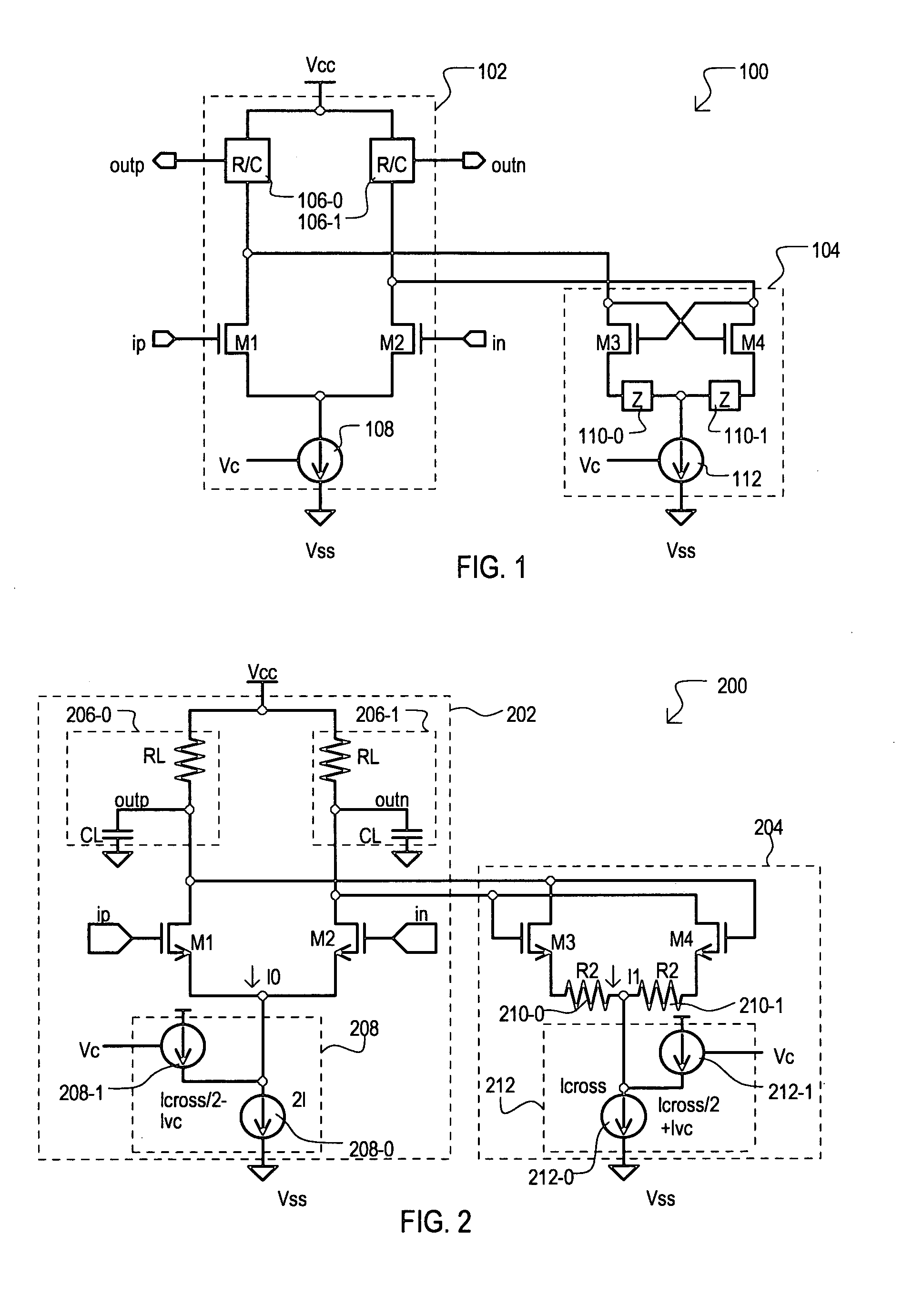
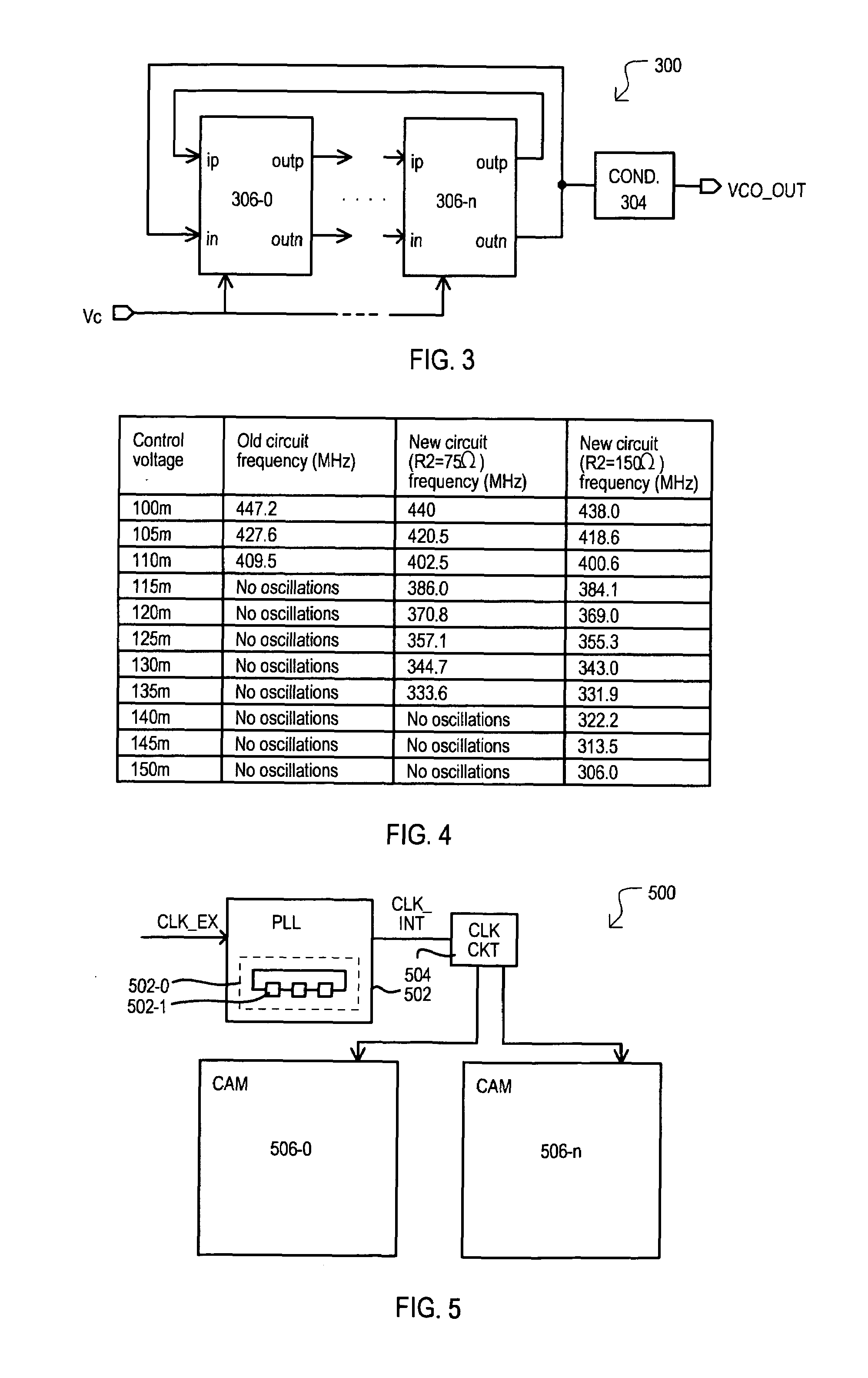
[0023]In the following description, for purposes of explanation, numerous specific details are set forth in order to provide a thorough understanding of the present invention. It will be evident, however, to one skilled in the art that the present invention may be practiced without these specific details. In other instances, well-known circuits, structures, and techniques may not be shown in detail or may be shown in block diagram form in order to avoid unnecessarily obscuring an understanding of this description.

[0024]Reference in the description to “one embodiment” or “an embodiment” means that a particular feature, structure, or characteristic described in connection with the embodiment is included in at least one embodiment of the invention. The appearance of the phrase “in one embodiment” in various places in the specification do not necessarily all refer to the same embodiment. The term “to couple” or “electrically connect” as used herein may include both to directly and to in...


PUM


Abstract

A delay cell circuit (200) is disclosed. The delay cell circuit may include a differential stage (202) and a cross-coupled stage (204). The cross-coupled stage can include resistors (210-0 and 210-1) the function to reduce a gain. The differential stage (202) and cross-coupled stage (204) can include variable currents sources (208 and 212), respectively. As frequency of operation increases, variable current source (208) provides a larger current to the differential stage (202) and variable current source (212) provides a smaller current to cross-coupled stage (204). Delay cell circuit (200) may be used in a voltage controlled oscillator (VCO). By including gain attenuating devices such as resistors (210-0 and 210-1), a frequency tuning range of the VCO may be increased.

Description

[0001]This application claims the benefit of U.S. provisional patent application Ser. No. 60 / 678,397, filed May 5, 2005, the contents of which are incorporated by reference herein.TECHNICAL FIELD[0002]The present invention relates generally to delay circuits, and more particularly to a voltage controlled delay circuit for use in a voltage controlled oscillator.BACKGROUND OF THE INVENTION[0003]Phase locked loop (PLL) circuits can be utilized in a wide variety of applications, including timing applications for integrated circuits. A typical PLL can include a phase detector that determines a phase difference between a received signal and a feedback signal, a loop filter that can derive a control voltage from the phase difference indicated by the phase detector, and a voltage controlled oscillator (VCO) that can generate a feedback signal having an oscillation frequency corresponding to the control voltage. In some arrangements, the VCO output signal may be frequency divided before bein...

Claims


Application Information

Patent Timeline
Patent Type & Authority Patents(United States)
IPC IPC(8): H03H11/26
CPCH03H11/265H03K3/0322H03K5/133H03L7/0995H03K2005/00208H03K2005/00234H03K2005/00026
Inventor SIVADASAN, MOHANDAS PALATHOLMANAROHILLA, GAJENDAR
Owner MONTEREY RES LLC
Why Eureka
Try Eureka