
Camera system for monitoring a solid angle region and for detection of detailed information from the solid angle region

a solid angle and camera system technology, applied in the field of cameras, can solve the problems of only reproducing objects far away from the convex mirror on the sensor in a small size and with little detail, and achieve the effect of stab positioning

Inactive Publication Date: 2008-07-15
METHYIGENE +1
View PDF21 Cites 5 Cited by
  • Summary
  • Abstract
  • Description
  • Claims
  • Application Information

AI Technical Summary

Benefits of technology

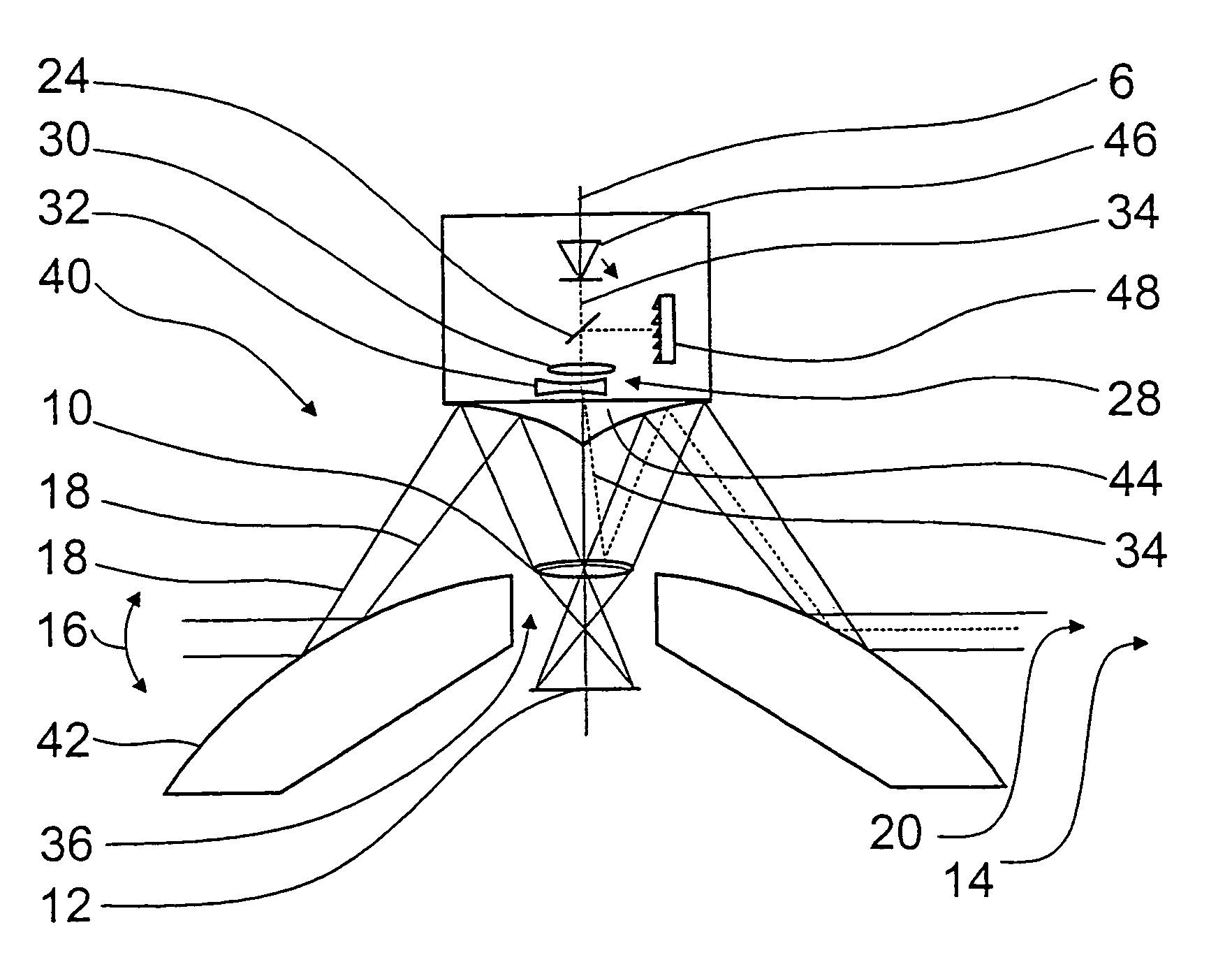
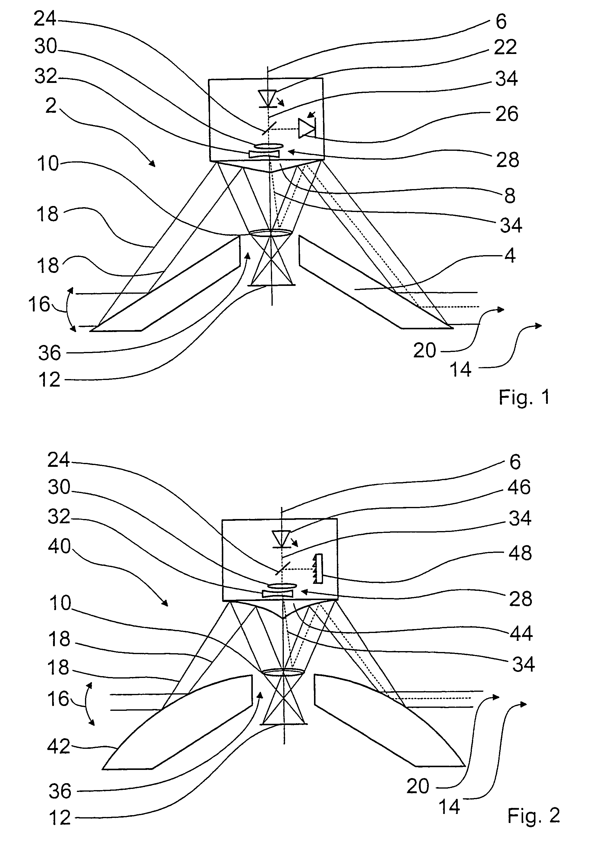
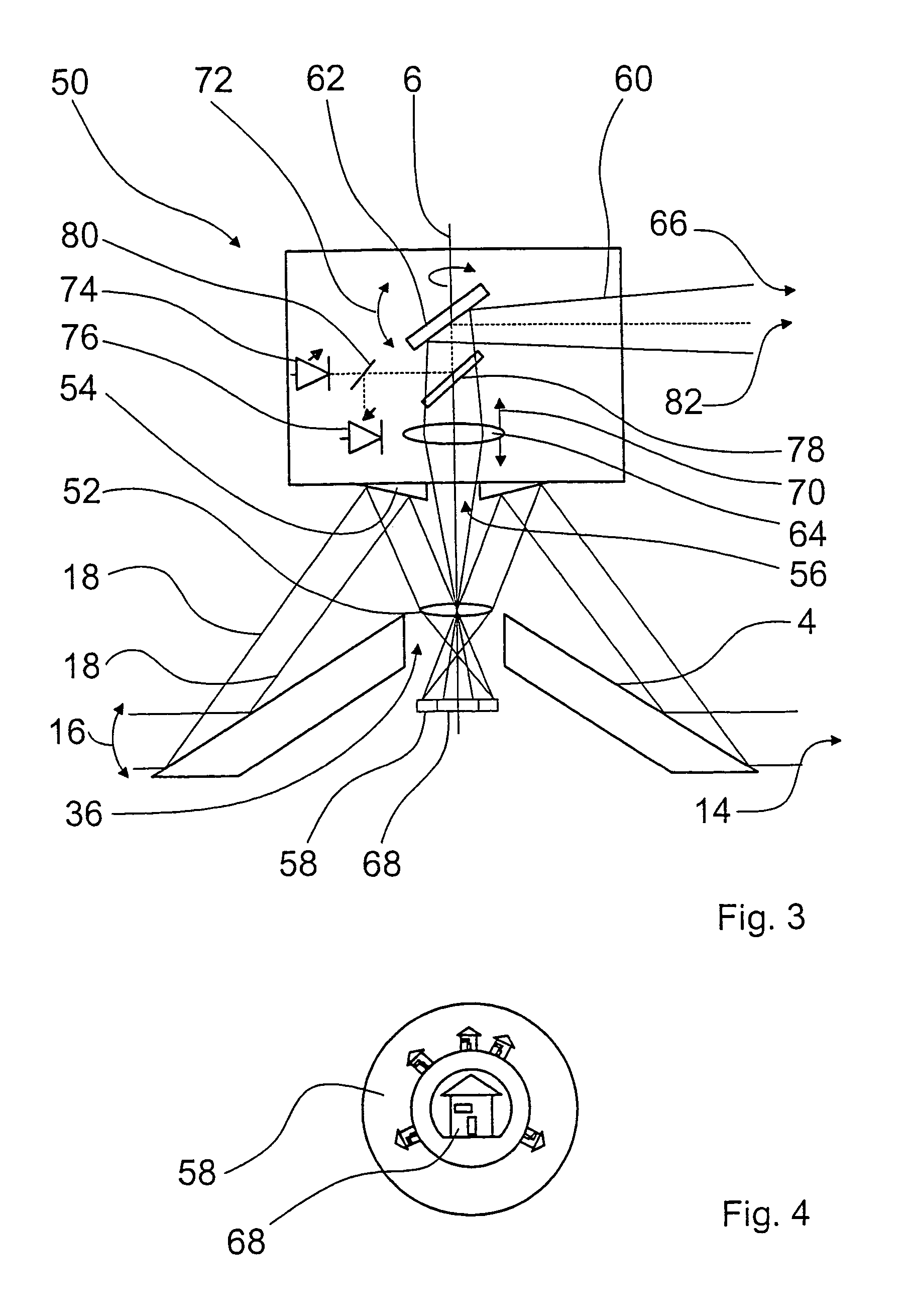
[0007]The invention is based on the consideration that detail information can be achieved in addition to a for example all-around view by a second camera system, whose field of view on to a partial region can be moved within the solid angle region covered by the first camera system. In this case the camera is directed on to the partial region which is of interest. Very precise pivotal movement of the detailed field of view on to the detailed partial region which is of interest is more easily possible if it is not the entire camera but only an optical element that has to be moved for pivotal direction on to the partial region which is of interest. In addition it is possible to save on components and costs, in comparison with two separate camera systems. In that way, in a camera system, the passive first optical system is supplemented by an active second optical system for detailed analysis of a partial region which is of particular interest.
[0018]Advantageously the convex mirror includes an opening through which the first beam path is passed. By virtue of that arrangement it is possible to use a dead space in which the sensor would otherwise form the image of itself. An optional arrangement of the sensor in the interior of the convex mirror can provide that it can be positioned stably and in a protected fashion.

Problems solved by technology

It will be noted however that the large solid angle region which can be viewed gives rise to the disadvantage that objects which are far away from the convex mirror are only reproduced on the sensor in a small size and with little detail.

Method used


Image

  • Camera system for monitoring a solid angle region and for detection of detailed information from the solid angle region
  • Camera system for monitoring a solid angle region and for detection of detailed information from the solid angle region
  • Camera system for monitoring a solid angle region and for detection of detailed information from the solid angle region

Examples


Embodiment Construction

[0026]FIG. 1 shows a camera system 2 with a first optical system for producing a panoramic view. A first optical system includes a convex mirror 4 which is in the form of an externally mirrored cone and which is arranged in rotationally symmetrical relationship about a longitudinal axis 6 of the camera system 2. The first optical system further includes a second mirror 8 which is also in the form of an externally mirrored cone and arranged in rotationally symmetrical relationship around the longitudinal axis 6. The mirror 8 and the convex mirror 4 are made from aluminium which is polished at its outside surface. It is also possible for the mirroring of the two mirrors 8, 4 to be produced by a thin silver or gold coating on a metal substrate. As a further optical element the first optical system includes a converging lens 10 for focusing an object, the image of which is to be formed, on a sensor 12. The sensor 12 is a matrix detector, also referred to as a focal plane array (FPA), wh...


PUM


Abstract

A camera system (2, 40, 50) including a sensor (12, 58) and a first optical system which includes a convex mirror (4, 42) and through which the image of a solid angle region (14) is producible on the sensor (12, 58) by way of a first beam path (18). In order, in addition to producing an image of a large solid angle region (14), to permit scanning or detailed representation of a smaller partial region (20, 66, 82) of the solid angle region (14), the camera system (2, 40, 50) includes a second optical system through which a partial region (20, 66, 82) of the solid angle region (14) is detectable by way of a second beam path (34, 60) on a detail sensor (68), wherein the detail region (20, 66, 82) is selectable by an optical element (28) which is movable relative to the sensors (12, 58, 68).

Description

BACKGROUND OF THE INVENTION[0001]1. Field of the Invention[0002]The invention concerns a camera system comprising a sensor and a first optical system which includes a convex mirror and through which the image of a solid angle region can be produced on the sensor by way of a first beam path.[0003]2. Discussion of the Prior Art[0004]For the purposes of monitoring large regions of space such as for example railway stations, airports, public places and squares, stadia and the like, camera systems are known which permit a view into a very large solid angle region—for example all around. The overview article ‘Omnidirectional Vision’, Proceedings of the Eighth International Symposium of Robotic Research, Hayama, Japan, Oct. 3-7, 1997, describes camera systems in which the beam path of an optical system is directed on to a convex mirror and in that way objects can be imaged on a sensor, from a very large solid angle region. In that case, the convex mirror used is in the form of a spherical ...

Claims


Application Information

Patent Timeline
IPC IPC(8): H04N5/225H04N9/04H04N7/18H04N9/47G02B13/06G02B17/08G03B37/02
CPCG02B13/06G03B37/02H04N5/23238H04N5/2259H04N5/2254H04N23/55H04N23/58H04N23/698
Inventor KROGMANN, DIRKMOLDENHAUER, KAITHOLL, HANS DIETER
Owner METHYIGENE
Learn More