Viewing angle control element, display device, and electronic apparatus

a control element and angle technology, applied in the direction of instruments, polarising elements, catheters, etc., can solve the problems of deterioration of usability in a usual use, and achieve the effect of bright display, easy reduction of device thickness, and bright display

Active Publication Date: 2008-07-15
BOE TECH GRP CO LTD
View PDF47 Cites 10 Cited by
  • Summary
  • Abstract
  • Description
  • Claims
  • Application Information

AI Technical Summary

Benefits of technology

[0022]According to this configuration, when the optical axis of the polarizing layers of the viewing angle control element and the optical axis of the liquid crystal display element are deviated from each other, the light transmitted through one polarizing layer can be converted into the light having a polarized direction parallel to the optical axis of the other polarizing layer by means of the optical rotation means, and then can be made incident on the other polarizing layer. Therefore, the light can be prevented from being absorbed between the viewing angle control element and the liquid crystal display element, so that it is possible to provide a display device capable of accomplishing a bright display.
[0023]In the display device according to the invention, the optical rotation device may be a half-wave plate, or may have twist-aligned liquid crystal. According to this configuration, the light can be prevented from being absorbed between the viewing angle control element and the liquid crystal display element, so that it is possible to provide a display device capable of accomplishing a bright display.
[0024]In the display device according to the invention, the display element may be an EL display element, a circularly polarizing layer may be provided between the EL display element and the viewing angle control element, and the polarizing layer of the viewing angle control element on the EL display element side may constitute a part of the circularly polarizing layer. According to this configuration, since the polarizer provided with the circularly polarizing layer can be allowed to function as the polarizing layer of the viewing angle control element, it is possible to easily accomplish decrease of the thickness of the device. Furthermore, a specular effect of the EL display element can be effectively prevented by means of operation of the circularly polarizing layer, so that a display with a high quality can be obtained.
[0025]An electronic apparatus according to the invention may include the viewing angle control element according to the present invention described above. Further, the electronic apparatus according to the invention may include the display device according to the present invention described above. Since the electronic apparatus includes the viewing angle control element or the display device according to the invention, a visible condition of information can be freely controlled by using the viewing angle control function of the viewing angle control element, so that it is possible to easily perform the concealment of information from a third party and to provide excellent visibility of information to the operator.

Problems solved by technology

However, in this construction of attaching the optical film, since works are performed always with a narrow viewing angle and brightness of display is a little dark as seen from the front thereof, deterioration of usability in a usual use results from the improved concealment of displayed images.

Method used


Image

  • Viewing angle control element, display device, and electronic apparatus
  • Viewing angle control element, display device, and electronic apparatus
  • Viewing angle control element, display device, and electronic apparatus

Examples


first embodiment

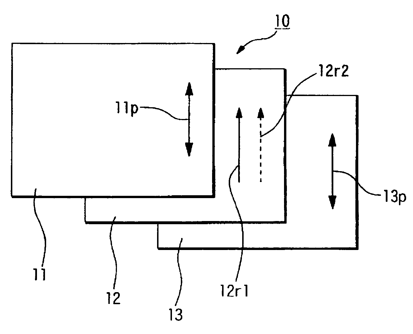
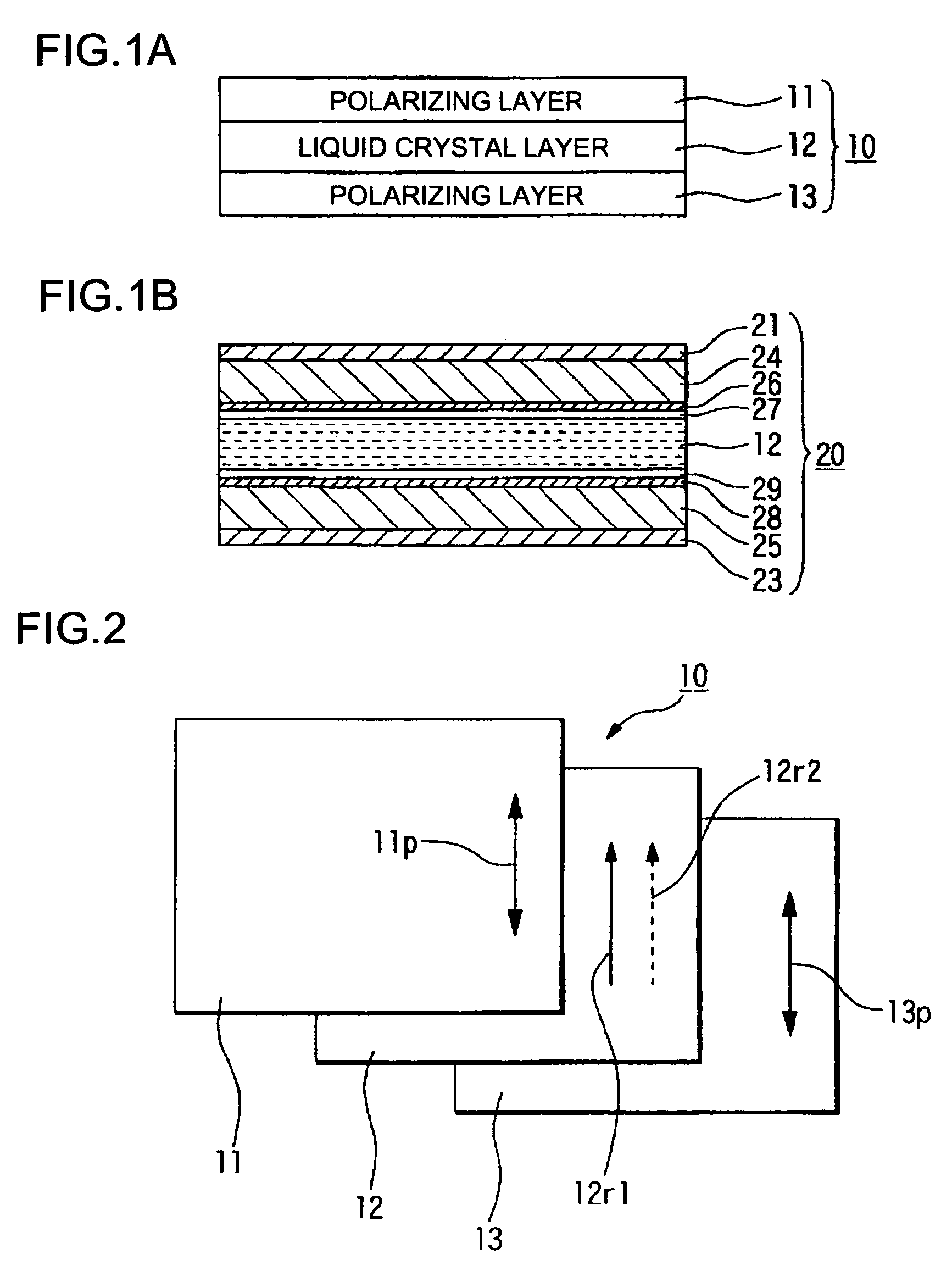
[0064]As a specific structural example of the viewing angle control element 30 according to this embodiment, the configuration shown in FIG. 1(b) can be applied. In other words, in the structural example shown in FIG. 1(b), by rotating the transmission axes of the polarizers 21, 23 by 90° from the arrangement of the first embodiment, the viewing angle control element having the basis structure shown in FIG. 5 can be obtained.

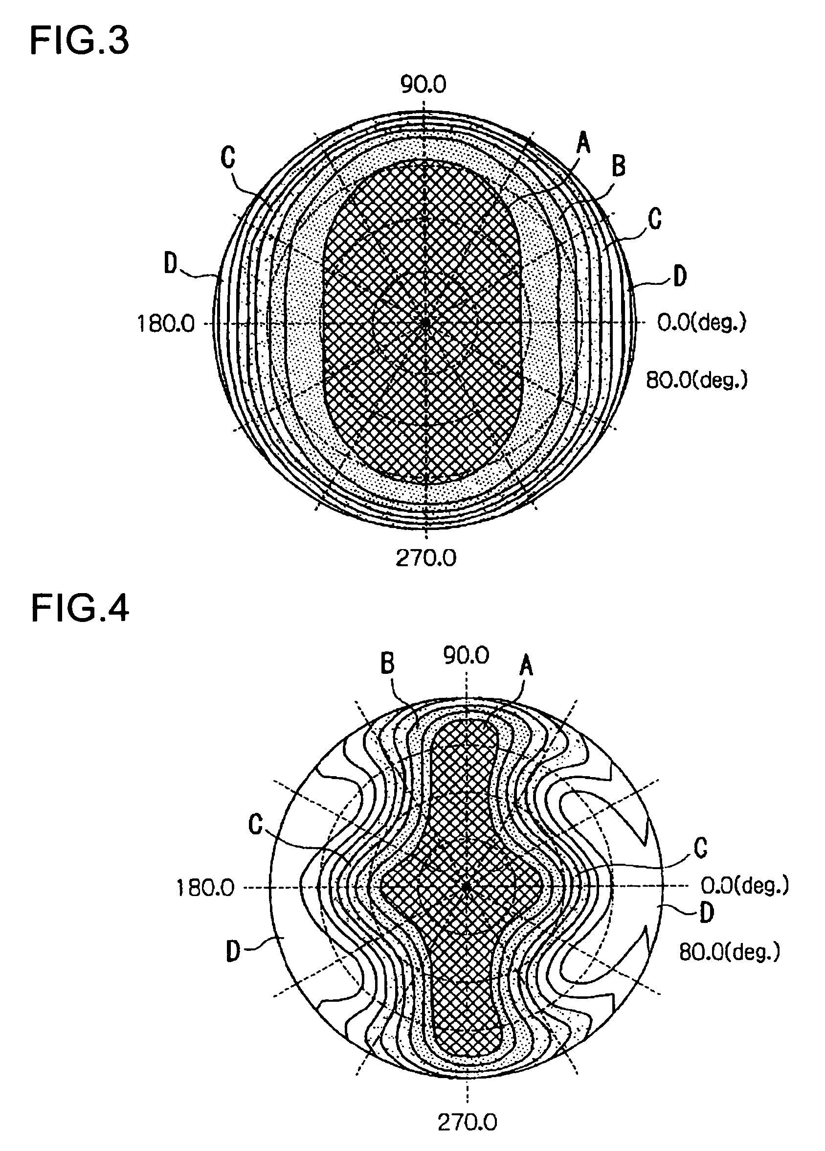
[0065]The inventor has measured the angle distribution of transmissivity of the viewing angle control element according to this embodiment, similarly to the first embodiment, and the measuring method is similar to the first embodiment. FIG. 6 shows the measurement result in a state where a voltage is not applied to the liquid crystal layer, and FIG. 7 shows the measurement result in a state where a voltage is applied to the liquid crystal layer (in a state where the liquid crystal molecules are aligned to be perpendicular to the polarizing layers 11, 13).

[0066]A...

fourth embodiment

[0071]Next, the invention will be described with reference to FIGS. 10 and 11. FIGS. 10 and 11 are schematic structural diagrams illustrating a display device comprising the viewing angle control element 20 according the aforementioned embodiment, where FIG. 10 shows an example where the viewing angle control element 20 is provided at the front surface side (an observer O side) of the display element 35a, and FIG. 11 shows an example where the viewing angle control element 20 is provided at the back surface side (a side opposite to an observer O) of the display element 35b.

[0072]First, in the display device shown in FIG. 10, a display is carried out on the observer O by allowing the display light L of the display element 35a to be transmitted through the viewing angle control element 20. Then, by electrically controlling the liquid crystal layer 12 of the viewing angle control element 20 according to the aforementioned embodiment, the emission angle (that is, viewing angle) of the ...

seventh embodiment

[0081]Next, the invention will be described with reference to FIGS. 15 to 17. In the display device according to this embodiment of which the sectional structure is shown in FIG. 15, the viewing angle control element 10 including the polarizing layers 11, 13 and the liquid crystal layer 12 interposed therebetween, and a liquid crystal display element 35 having the polarizing layers 38, 39 and a liquid crystal layer 36 interposed therebetween are laminated with an optical rotation element (optical rotation means) 40 therebetween. In the display device according to this embodiment, the viewing angle is controlled by the viewing angle control element 10, and then the light L of a light source, etc. incident on the viewing angle control element 10 is allowed to be incident on the optical rotation element 40. Then, in a state where a polarized direction of the light L is rotated by the optical rotation element 40, and thus the transmission axis of the polarizing layer 38 of the liquid cr...


PUM

PropertyMeasurementUnit
thicknessaaaaaaaaaa
thicknessaaaaaaaaaa
thicknessaaaaaaaaaa

Abstract

The invention provides a viewing angle control element capable of realizing high information concealment without damaging brightness of transmitted light and dynamically changing a viewing angle in accordance with need or no need of information concealment. The viewing angle control element according to the invention can include liquid crystal twist-aligned by approximately 180°, and have a liquid crystal layer being electrically controllable and a pair of polarizing layers provided at both sides of the liquid crystal layer. Optical axes of both polarizing layers can be arranged to be substantially parallel to each other, and liquid crystal molecules of the liquid crystal layer adjacent to the polarizing layers can be aligned to be substantially parallel to the optical axes of the polarizing layers.

Description

BACKGROUND OF THE INVENTION[0001]1. Field of Invention[0002]The present invention relates to a viewing angle control element, a display device, and an electronic apparatus.[0003]2. Description of Related Art[0004]In general, image display devices provided in word processors, computers, or the like, display manipulation result of an operator together with various data on screens. In such image display devices, the brightness, the contrast ratio and the width of viewing angle of display are required, and with enhancement of such characteristics, works can be easily performed and fatigue due to the works can be reduced. On the other hand, recently, when secrecy of works is high or when computers or mobile phones are used in public places of public transportation such as trains or buses, image display devices having techniques for concealing the displayed image from persons around the operator have been required more and more. In this use, even if the image display devices have high dis...

Claims


Application Information

Patent Timeline
Patent Type & Authority Patents(United States)
IPC IPC(8): G02F1/1347G02F1/13G02F1/1335G02B5/30G02F1/133G02F1/13363H01L51/50H05B33/02
CPCG02F1/1323G02F1/13471G02F1/1347A61M5/158A61M25/0637A61M2005/1586
Inventor MATSUSHIMA, TOSHIHARU
Owner BOE TECH GRP CO LTD
Why Eureka
Try Eureka