Hybrid cooling system and method for a multi-component electronics system

a technology of electronic systems and hybrid cooling, applied in the direction of domestic cooling apparatus, power cables, cables, etc., can solve the problems of unmanageable approach at the frame level, the sensible heat load carried by the air exiting the frame will eventually exceed the ability of room air conditioning to effectively handle the load, etc., to achieve the effect of facilitating cooling

Active Publication Date: 2008-07-15
INT BUSINESS MASCH CORP
View PDF12 Cites 52 Cited by
  • Summary
  • Abstract
  • Description
  • Claims
  • Application Information

AI Technical Summary

Problems solved by technology

This trend poses a cooling challenge at both the module and system level.
However, this approach is becoming unmanageable at the frame level in the context of a computer installation (e.g., data center).
The sensible heat load carried by the air exiting the frame will eventually exceed the ability of room air conditioning to effectively handle the load.
In such installations, not only will the room air conditioning be challenged, but the situation may also result in recirculation problems with some fraction of the “hot” air exiting one frame being drawn into the air inlet of the same or a nearby frame.
Furthermore, while the acoustic noise level of a powerful (or higher RPM) air moving device in a single drawer may be within acceptable acoustic limits, because of the number of air moving devices in the frame, the total acoustic noise at the frame level may not be acceptable.
In addition, the conventional openings in the frame for the entry and exit of air flow make it difficult, if not impossible to provide effective acoustic treatment to reduce the acoustic noise level outside the frame.
Finally, as operating frequencies continue to increase, electromagnetic cross talk between tightly spaced computer frames is becoming a problem largely due to the presence of the openings in the covers.

Method used


Image

  • Hybrid cooling system and method for a multi-component electronics system
  • Hybrid cooling system and method for a multi-component electronics system
  • Hybrid cooling system and method for a multi-component electronics system

Examples


Embodiment Construction

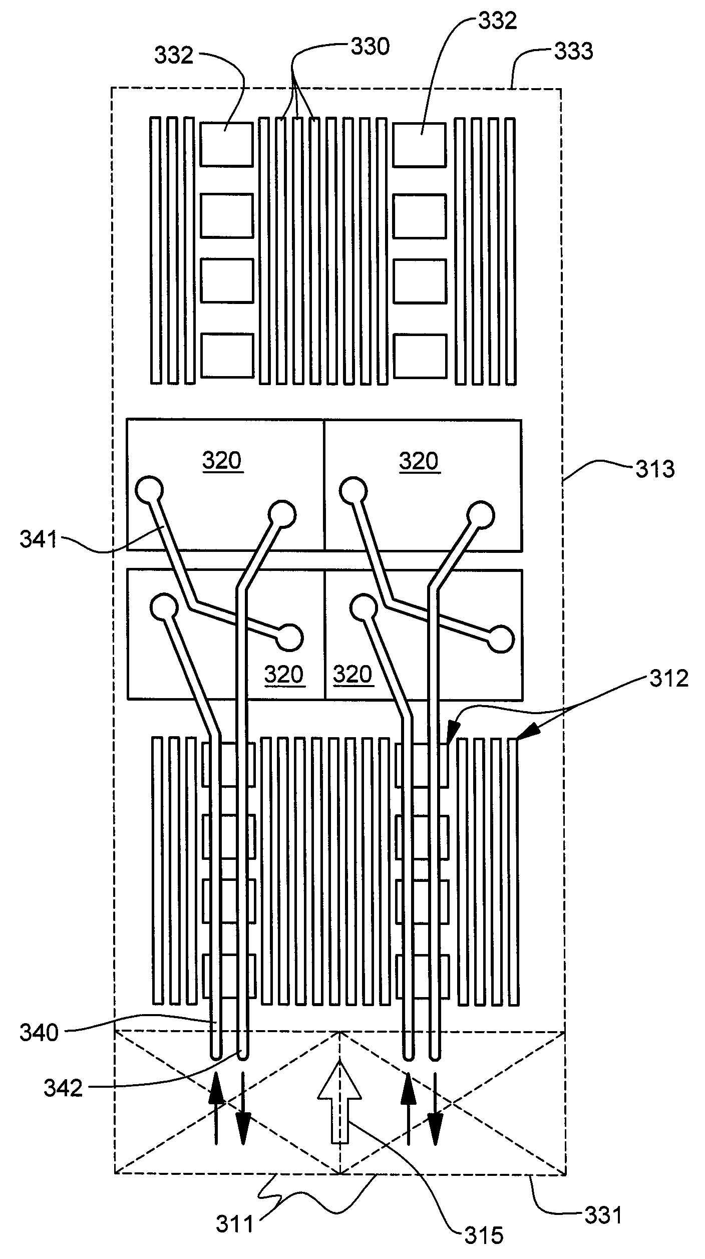
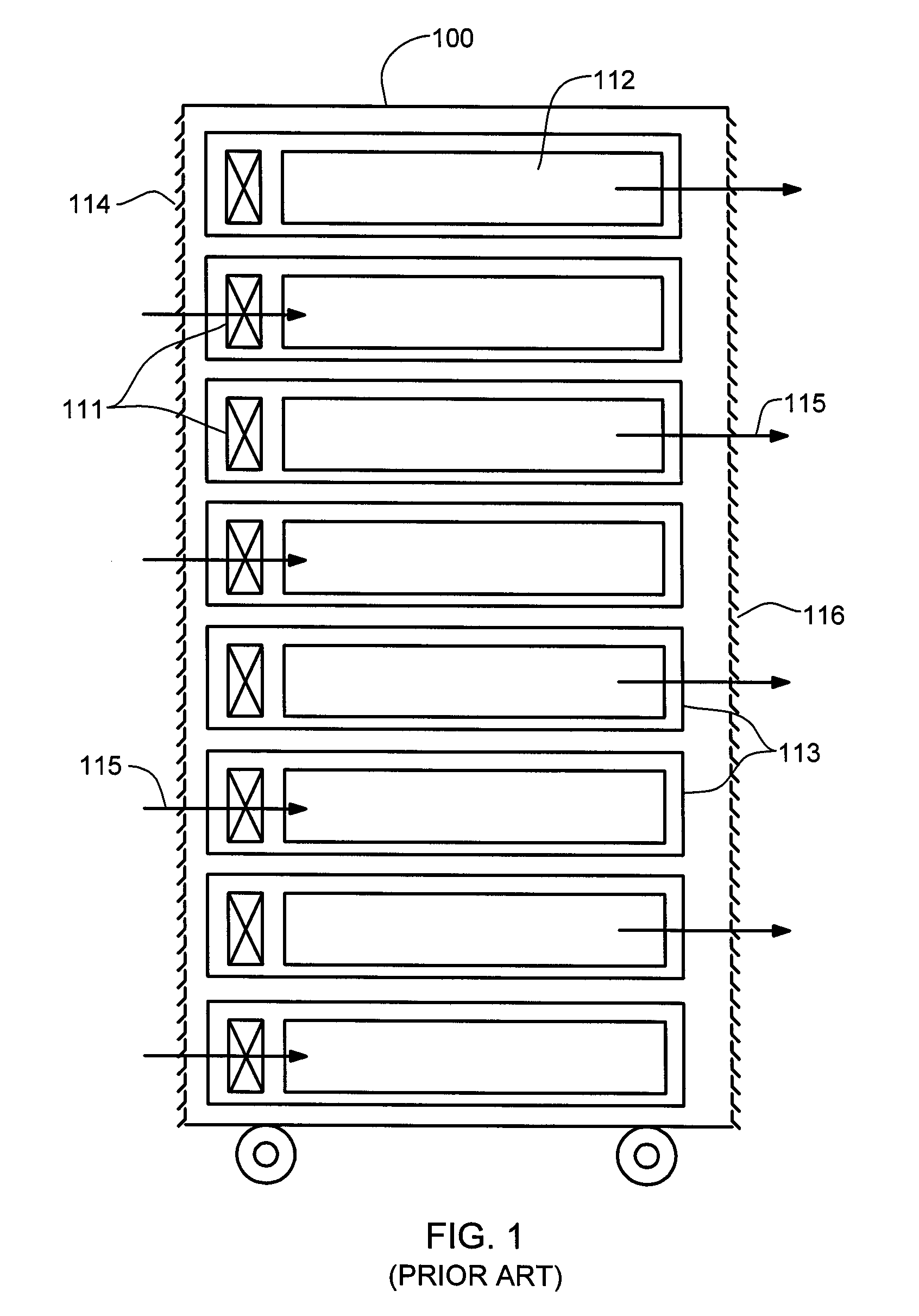
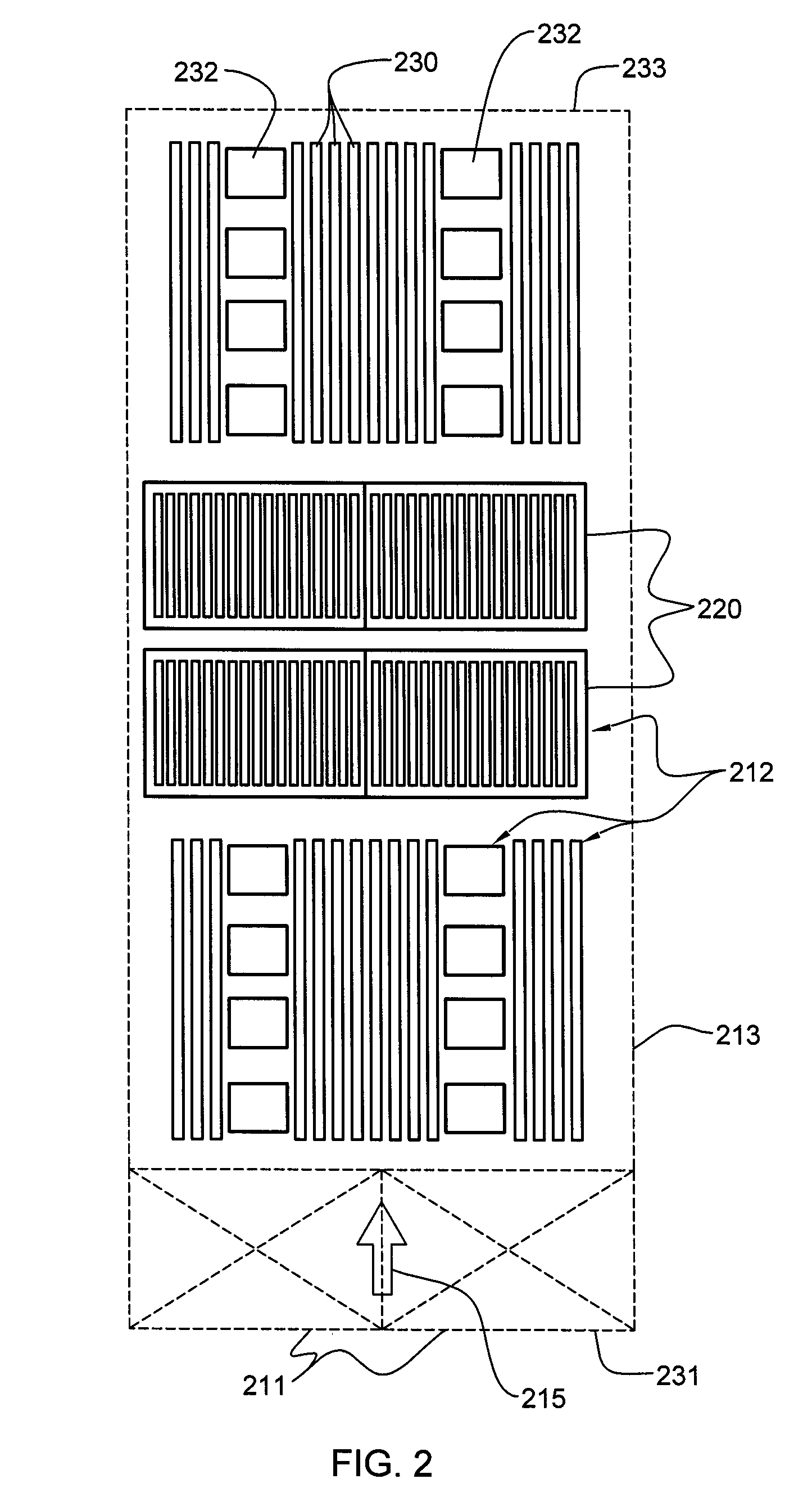
[0025]As used herein “electronics system” comprises any system containing one or more heat generating components of a computer system or other electronics unit requiring cooling. The terms “electronics rack”, “electronics frame”, and “frame” are used interchangeably, and include any housing, rack, compartment, blade chassis, etc., having heat generating components of a computer system or electronics system and may be for example, a stand-alone computer processor having high, mid or low end processing capability. In one embodiment, an electronics frame comprises multiple electronics drawers, each having multiple heat generating components disposed therein requiring cooling. “Electronics drawer” refers to any sub-housing, blade, book, drawer, node, compartment, etc., having multiple heat generating electronics components disposed therein. Each electronics drawer of an electronics frame may be movable or fixed relative to the electronics frame, with rack mounted electronics drawers and...


PUM


Abstract

A hybrid cooling system and method of fabrication are provided for a multi-component electronics system. The cooling system includes an air moving device for establishing air flow across at least one primary and at least one secondary heat generating component to be cooled; and a liquid-based cooling subsystem including at least one cold plate, physically coupled to the at least one primary heat generating component, and a thermally conductive coolant-carrying tube in fluid communication with the at least one cold plate. A thermally conductive auxiliary structure is coupled to the coolant-carrying tube and includes a plurality of thermally conductive fins extending from a surface thereof. The plurality of thermally conductive fins are disposed at least partially over the at least one secondary heat generating component to be cooled, and provide supplemental cooling of at least a portion of the air flow established across the multiple components of the electronics system.

Description

CROSS-REFERENCE TO RELATED APPLICATIONS[0001]This application contains subject matter which is related to the subject matter of the following applications, each of which is assigned to the same assignee as this application and each of which is hereby incorporated herein by reference in its entirety:[0002]“Cooling System and Method for a Multi-Component Electronics System Employing Conductive Heat Transport”, Campbell et al., Ser. No. 11 / 539,905;[0003]“Method of Assembling a Cooling System for a Multi-Component Electronics System”, Campbell et al., Ser. No. 11 / 539,907;[0004]“Liquid-Based Cooling System for Cooling a Multi-Component Electronics System”, Campbell et al., Ser. No. 11 / 539,910;[0005]“Method and Apparatus for Mounting a Heat Sink in Thermal Contact with an Electronic Component”, Colbert et al, Ser. No. 11 / 201,972, filed Aug. 11, 2005; and[0006]“Heatsink Apparatus for Applying a Specified Compressive Force to an Integrated Circuit Device”, Colbert et al, Ser. No. 11 / 460,334...

Claims


Application Information

Patent Timeline
Patent Type & Authority Patents(United States)
IPC IPC(8): H05K7/20
CPCH05K7/20772H05K7/20554H05K7/20736H05K7/20009F28F1/20F28F1/22
Inventor CAMPBELL, LEVI A.CHU, RICHARD C.ELLSWORTH, JR., MICHAEL J.IYENGAR, MADHUSUDAN K.SCHMIDT, ROGER R.SIMONS, ROBERT E.
Owner INT BUSINESS MASCH CORP
Why Eureka
Try Eureka