
Reduced-weight fuel system for gas turbine engine, gas turbine engine having a reduced-weight fuel system, and method of providing fuel to a gas turbine engine using a reduced-weight fuel system

a gas turbine engine and fuel system technology, which is applied in the ignition of the turbine/propulsion engine, engine starters, lighting and heating apparatus, etc., can solve the problems of reducing the ability of the engine to be reliably restarted, affecting the reliability of the windmill, and reducing the ability of the fuel pump to supply the engine with fuel under normal operating conditions

Active Publication Date: 2008-07-22
HONEYWELL INT INC
View PDF16 Cites 24 Cited by
  • Summary
  • Abstract
  • Description
  • Claims
  • Application Information

AI Technical Summary

Benefits of technology

The present invention provides a fuel system for a gas turbine engine that can supply fuel at different rates for engine start up. The fuel system includes a main fuel pump and an auxiliary fuel pump that provide fuel to the engine at different rates. This allows for efficient fuel supply during engine start up and windmilling, and ensures a reliable and safe operation of the gas turbine engine.

Problems solved by technology

It is generally desirable to turn an engine shaft at about 10 percent of its rated speed during engine start-up; at lower speeds starting may be difficult because, for example, the fuel pump may provide fuel at too low a rate for a reliable start.
Other variables, such as airspeed when the restart becomes necessary, may further reduce the ability of the engine to be reliably windmill restarted.
However, a fuel pump capable of supplying an engine with fuel under normal operating conditions may not supply adequate fuel for a windmill start.
Using a fuel pump larger than is required for normal engine operation increases the weight and cost of a gas turbine engine.
Furthermore, such a large fuel pump generates more heat than would be produced by a smaller fuel pump.
This heat must be absorbed or dissipated by various heat sinks, such as the fuel supply, in the gas turbine engine, and this limits the amount of heat that these sinks can absorb from other sources.

Method used


Image

  • Reduced-weight fuel system for gas turbine engine, gas turbine engine having a reduced-weight fuel system, and method of providing fuel to a gas turbine engine using a reduced-weight fuel system
  • Reduced-weight fuel system for gas turbine engine, gas turbine engine having a reduced-weight fuel system, and method of providing fuel to a gas turbine engine using a reduced-weight fuel system
  • Reduced-weight fuel system for gas turbine engine, gas turbine engine having a reduced-weight fuel system, and method of providing fuel to a gas turbine engine using a reduced-weight fuel system

Examples


Embodiment Construction

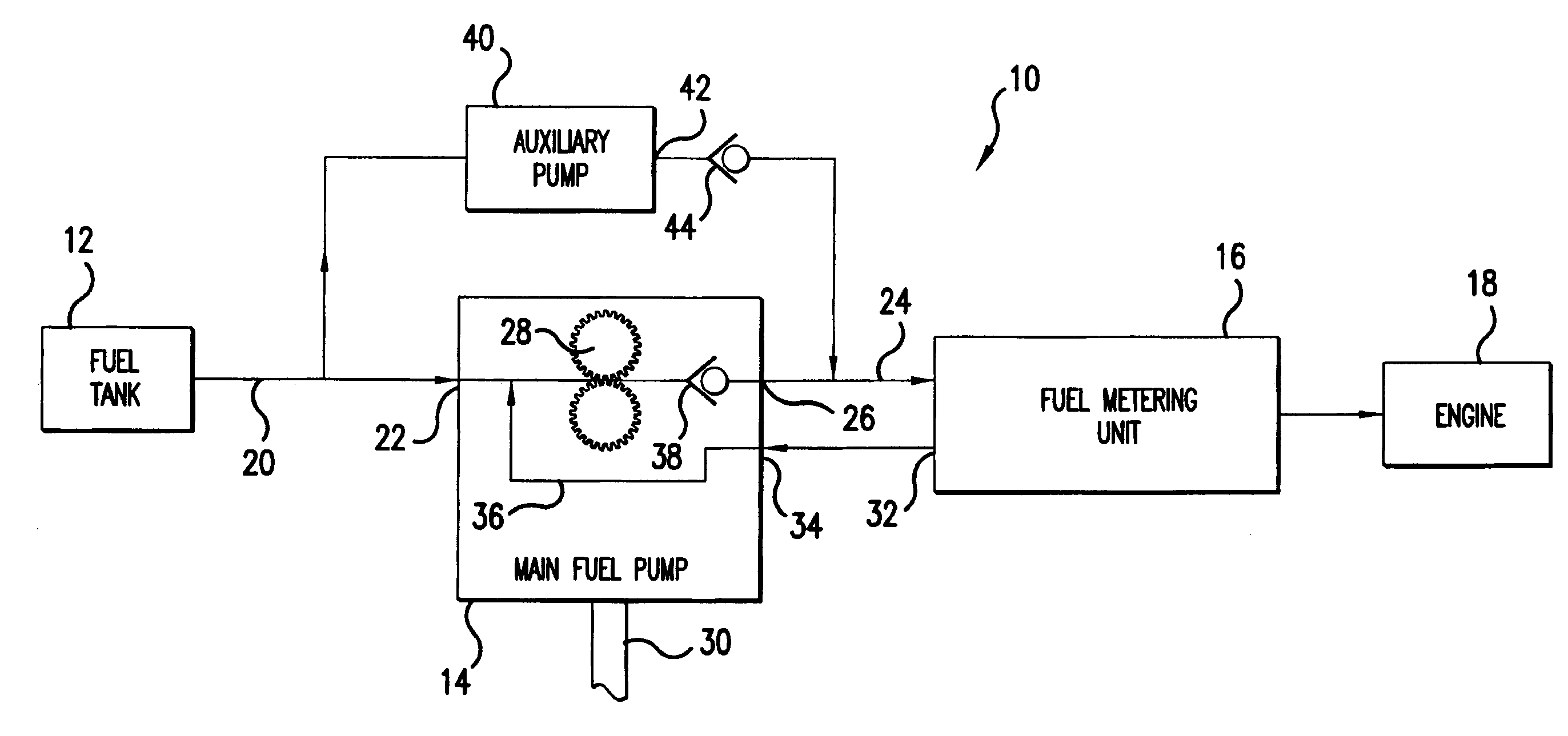
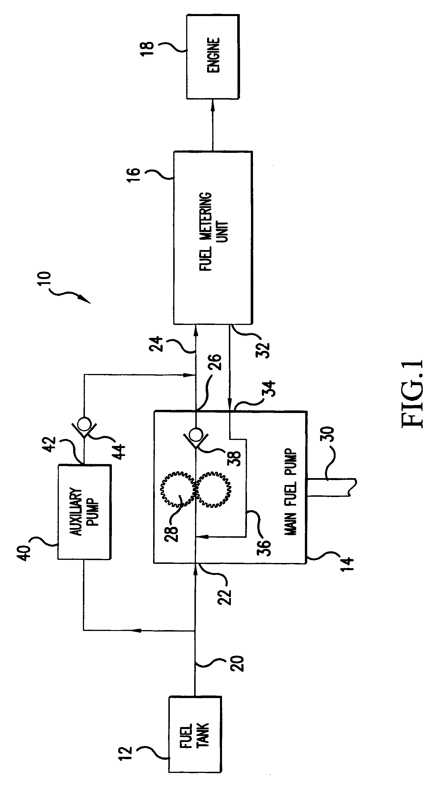
[0014]Referring now to the drawings, wherein the showings are for purposes of illustrating preferred embodiments of the invention only and not for the purpose of limiting same, FIG. 1 schematically illustrates an aircraft fuel system 10 comprising a fuel tank 12, a main fuel pump 14, and a fuel metering unit 16 providing fuel to an engine 18. A main fuel pump input fuel line 20 connects the fuel tank 12 to a first input 22 of the main fuel pump 14, and a main fuel pump output fuel line 24 leads from main fuel pump output 26 to fluid metering unit 16. Main fuel pump 14 comprises a gear pump and includes gears 28 driven by a shaft 30 powered by the rotation of engine 18 in a well-known manner.

[0015]Because gears 28 pump fuel at a rate based on engine speed, main fuel pump 14 often provides fuel at a rate greater than the rate required by fuel metering unit 16 or engine 18. Therefore, fuel metering unit 16 includes a recirculation output 32 for returning unneeded fuel to a recirculatio...


PUM


Abstract

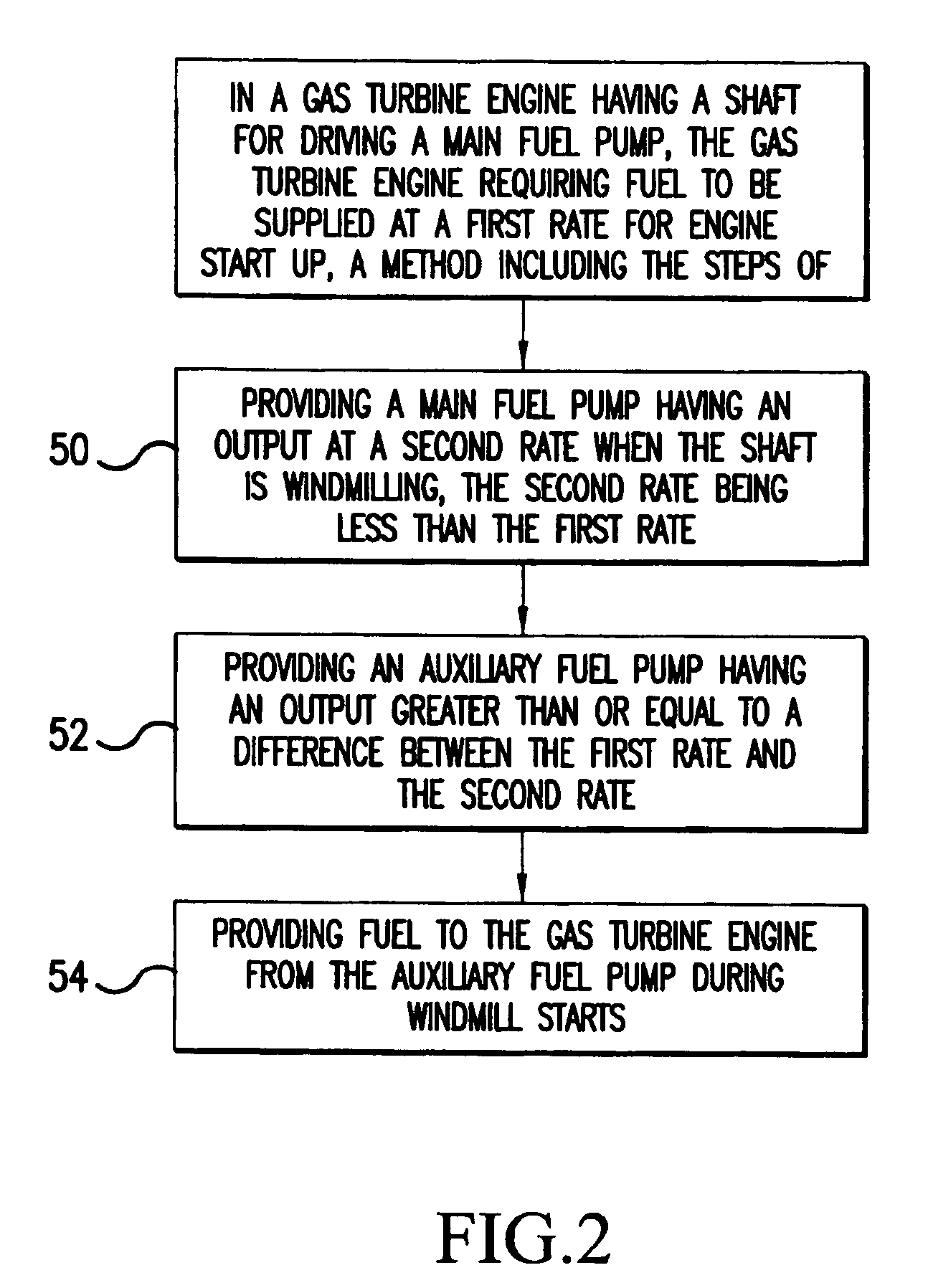
A fuel system (10) for a gas turbine engine (18) having a shaft (30) and requiring fuel to be supplied at a first rate for engine start up, the fuel system (10) including: a main fuel pump (14) for providing fuel to the gas turbine engine (18), the main fuel pump (14) having an output varying with shaft speed, the output being at a windmilling rate when the engine (18) is windmilling, the windmilling rate being less than the first rate; and an auxiliary fuel pump (40) for providing fuel to the gas turbine engine (18) and having an auxiliary output rate greater than or equal to the difference between the first rate and the windmilling rate. A method of operating such a fuel system (10) is also disclosed.

Description

FIELD OF THE INVENTION[0001]The present invention is directed to an improved fuel system for a gas turbine engine, a gas turbine engine including such an improved fuel system and a method of providing fuel to a gas turbine engine using an improved fuel system, and, more specifically, toward a reduced-weight fuel system for a gas turbine engine including an auxiliary fuel pump, a gas turbine engine including a reduced-weight fuel system having an auxiliary fuel pump, and a method of supplying fuel to a gas turbine engine using a reduced-weight fuel system including an auxiliary fuel pump.BACKGROUND OF THE INVENTION[0002]Gas turbine engines, such as those found on jet aircraft, comprise a housing within which fuel and air are combined and burned. Such engines generally include vanes for drawing air into the housing and a compressor that compresses the air and sends it to a gas generator. In the gas generator, a precisely metered supply of fuel is mixed with the compressed air and burn...

Claims


Application Information

Patent Timeline
Patent Type & Authority Patents(United States)
IPC IPC(8): F02C7/236
CPCF02C7/236F02C7/262F23K5/142F23R3/28F05D2260/85Y02T50/671F05D2270/092Y02T50/60
Inventor EICK, CHRISTOPHER D.MAHONEY, TIMOTHY D.JONES, DAVID D.LORENZ, WILLIAM
Owner HONEYWELL INT INC
Learn More