Motorized patient support for eye examination or treatment

a patient support and motorized technology, applied in the field of head support and positioning apparatus and methods, can solve problems such as inability to be carried out, and achieve the effects of less intimidating, fast and accurate automatic movement, and less confining

Active Publication Date: 2008-07-22
CARL ZEISS MEDITEC INC
View PDF31 Cites 49 Cited by
  • Summary
  • Abstract
  • Description
  • Claims
  • Application Information

AI Technical Summary

Benefits of technology

[0007]Systems and methods in accordance with various embodiments of the present invention can overcome these and other deficiencies in existing head-positioning approaches. In one embodiment, a compact, motorized head supporting and positioning apparatus for eye examination and / or treatment is disclosed, which shall hereinafter be referred to as a Motorized Patient Support (MPS). An MPS apparatus can include head-receiving supports, such as a single-arm forehead rest and a chinrest, as well as a main assembly mounted with respect to an eye examination / treatment instrument, and a motor assembly, which can include a number of individual motors driven in a coupled manner, to guide the head of a patient to a desired position along any three-dimensional path. Various embodiments allow the three-dimensional movement to be performed at various speeds, in order to provide a level of comfort for the patient. While open-loop operation of the disclosed apparatus can be obtained using such a system, it can also be desirable to use a motorized patient support module with an eye tracking system to achieve closed-loop positioning or repositioning of an eye in real time.
[0008]In one aspect of an embodiment in accordance with the present invention, the forehead rest is linked to the corresponding base through a single arm assembly on one side of the to-be-positioned head. Unlike existing head positioning systems which utilize two arms, one on each side of the head, the use of a single arm provides open access to one side of the head, which is less confining and can be less intimidating for a patient when placing his or her head on the head rest assembly. It also can be easier for a doctor to visually check the eye level, as well as to manually manipulate an eyelid or an optical element positioned next to the eye. In addition, a forehead rest can be easily covered with a disposable slid-over plastic sleeve or other covering device for hygienic protection of the forehead rest, which would not be possible if an arm existed on both sides of the headrest.
[0009]Another aspect of one embodiment is to provide a motorized, three-dimensionally movable head support module. A unique feature of such an embodiment is the compactness of the head support module, which can be realized, for example, using a pivoted approximate longitudinal or Z-axis motion of the module with respect to the eye examination / treatment instrument. Owing to the fact that a pivoted Z-axis movement is not a true linear movement, a correction can be made through a compensating vertical or Y-axis movement. By coupling the motions of the motors of a motor module, such as a motor for each of the three axes, the head of the patient can be moved along a desired three-dimensional path at a speed, and with a smooth motion, that is comfortable to the patient.

Problems solved by technology

In addition, a forehead rest can be easily covered with a disposable slid-over plastic sleeve or other covering device for hygienic protection of the forehead rest, which would not be possible if an arm existed on both sides of the headrest.

Method used


Image

  • Motorized patient support for eye examination or treatment
  • Motorized patient support for eye examination or treatment
  • Motorized patient support for eye examination or treatment

Examples


Embodiment Construction

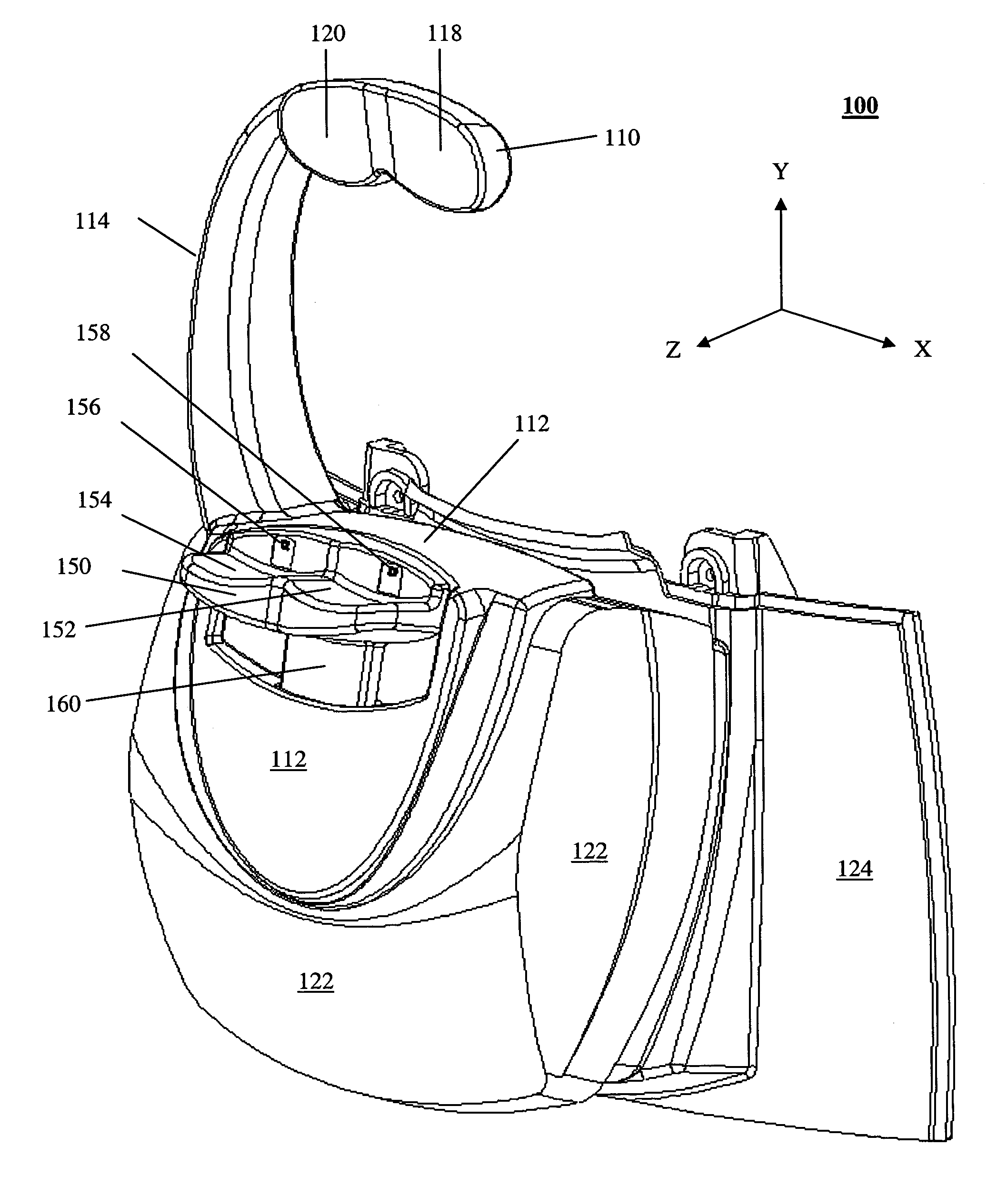
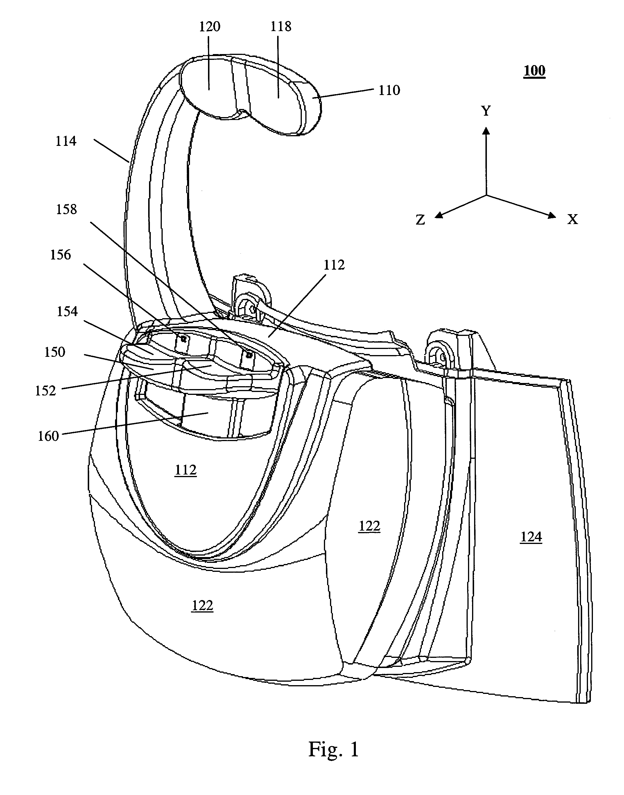
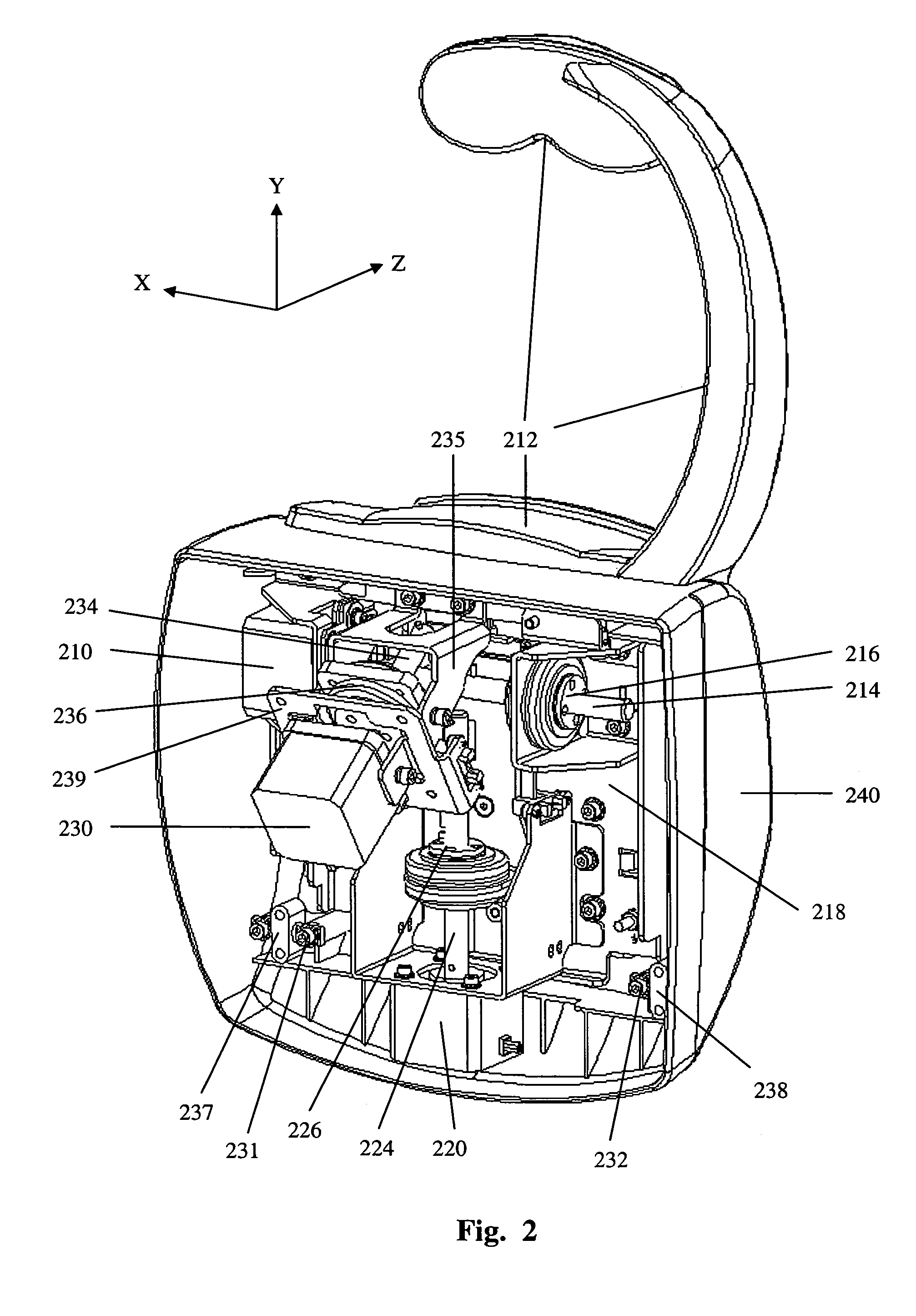
[0018]Systems and methods in accordance with various embodiments of the present invention can overcome deficiencies in existing head positioning systems by utilizing a motorized, three-dimensionally-movable patient head support. Such a support can be combined with an accurate eye tracking sensor system to provide a closed-loop system that, in real time, can constantly move the head of a patient back into position. Such a system also can take into consideration the fact that the patient can move his or her head while the head is being repositioned, such that there will be moments, or time durations, during which the eye of the patient is in the desired position. When this occurs, the eye examination / treatment instrument can be activated to conduct and / or complete the eye examination and / or treatment.

[0019]One embodiment in accordance with the present invention includes a compact motorized patient support (MPS) apparatus, which can be attached to an eye examination / treatment instrumen...


PUM


Abstract

A motorized head supporting and positioning apparatus is disclosed, such as is useful for eye examination or treatment. The apparatus includes head-receiving supports, which can include a forehead rest and a chinrest, which can be linked by a single arm assembly. A main assembly of the apparatus contains a motor assembly, which can include three motors driven in a coupled manner to guide a head along a three-dimensional path at a speed that is comfortable to the patient. The apparatus can be relatively compact, owing at least in part to a pivoted approximate Z-axis movement along the optical axis. In addition to open-loop operation, the apparatus can be used with a tracking subsystem to achieve closed-loop positioning in real time, as well as to enable the activation of an examination / treatment instrument when the eye is brought within an acceptable tolerance of a desired position.

Description

TECHNICAL FIELD OF THE INVENTION[0001]The present invention relates to head supporting and positioning apparatus and methods, such as may be useful for eye examination and / or treatment.BACKGROUND[0002]An apparatus for eye examination and treatment requires that a patient's eye be fixed in position with respect to the eye examination or treatment instrument. There is thus a need to initially and preliminarily position the patient head to approximately align the eye, and then to engage some fine adjustment to accurately align the selected eye (or both eyes) with the eye examination or treatment instrument.[0003]Due to the fact that the head size and the relative position of the eye(s) with respect to the chin are different for different patients, it is necessary to adjust the head support to accommodate the various physical characteristics of a patient's head. Some prior art solutions are based on a relative positional adjustment of the chinrest with respect to the forehead rest, whic...

Claims


Application Information

Patent Timeline
Patent Type & Authority Patents(United States)
IPC IPC(8): A61B3/00A61B3/113
CPCA61B3/0083A61B3/113
Inventor BAKER, CHRISARIANTA, KABIR
Owner CARL ZEISS MEDITEC INC
Why Eureka
Try Eureka