OLED device having improved contrast

a light-emitting diode and oled technology, applied in the direction of discharge tube luminescnet screen, discharge tube/lamp details, organic semiconductor device, etc., can solve the problems of affecting the effectiveness of circular polarizers, affecting the efficiency of circular polarizers, and capturing significant portions of emitted light in oled devices, so as to achieve the effect of increasing the ambient contrast of an oled devi

Active Publication Date: 2008-07-22
GLOBAL OLED TECH
View PDF8 Cites 84 Cited by
  • Summary
  • Abstract
  • Description
  • Claims
  • Application Information

AI Technical Summary

Problems solved by technology

As is known in the prior art, circular polarizers can greatly reduce the reflected ambient light, but such circular polarizers are expensive.
Significant portions of emitted light may also be trapped in OLED devices.
Scattering layers may be employed to improve the light emission of OLED devices, but may inhibit the effectiveness of circular polarizers, and do not selectively absorb ambient light.
However, this reduces the amount of area available for a black matrix, thereby increasing the amount of ambient light reflected from the OLED back electrode and reducing the contrast of a top-emitting OLED device.

Method used


Image

  • OLED device having improved contrast
  • OLED device having improved contrast
  • OLED device having improved contrast

Examples


Embodiment Construction

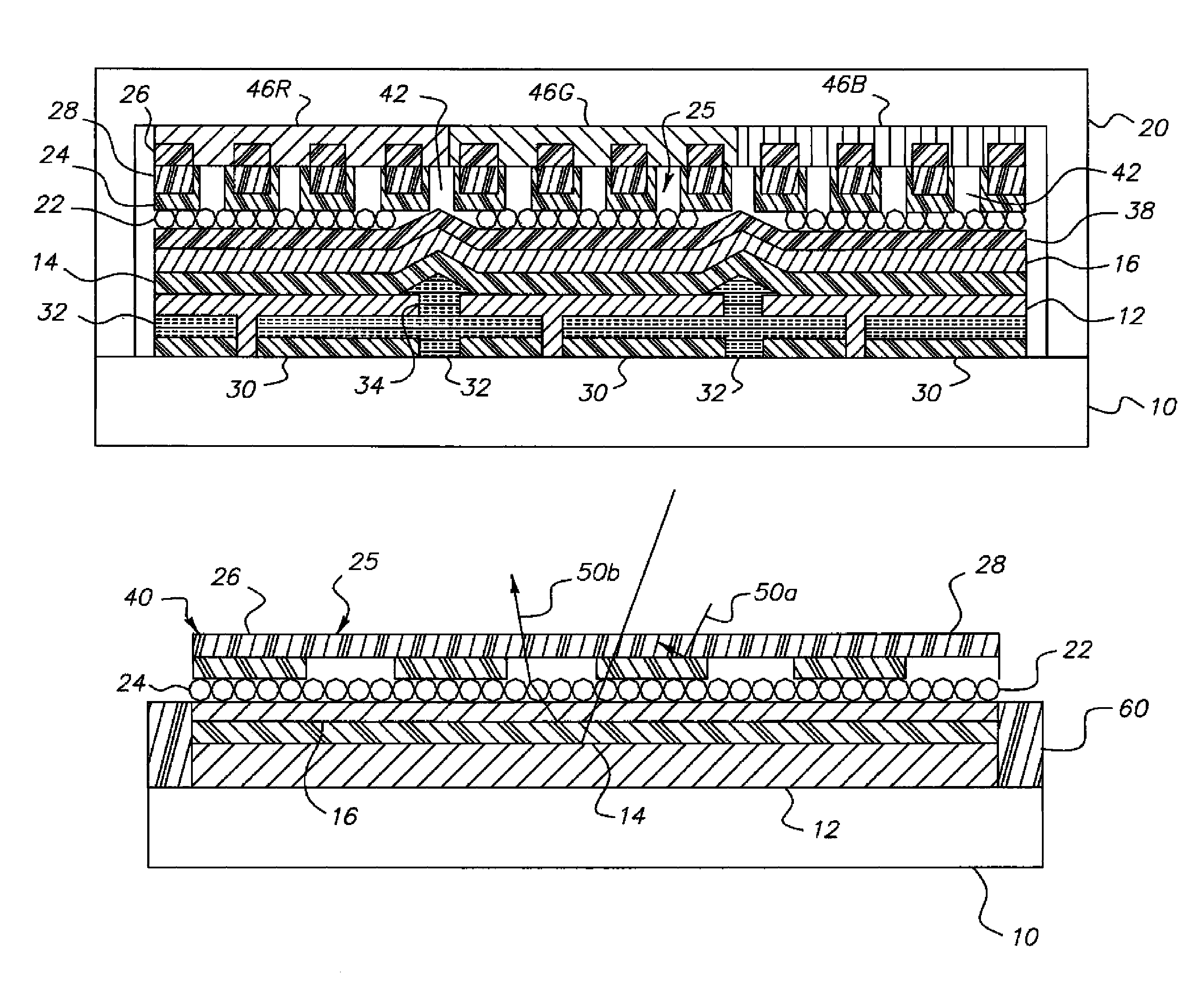
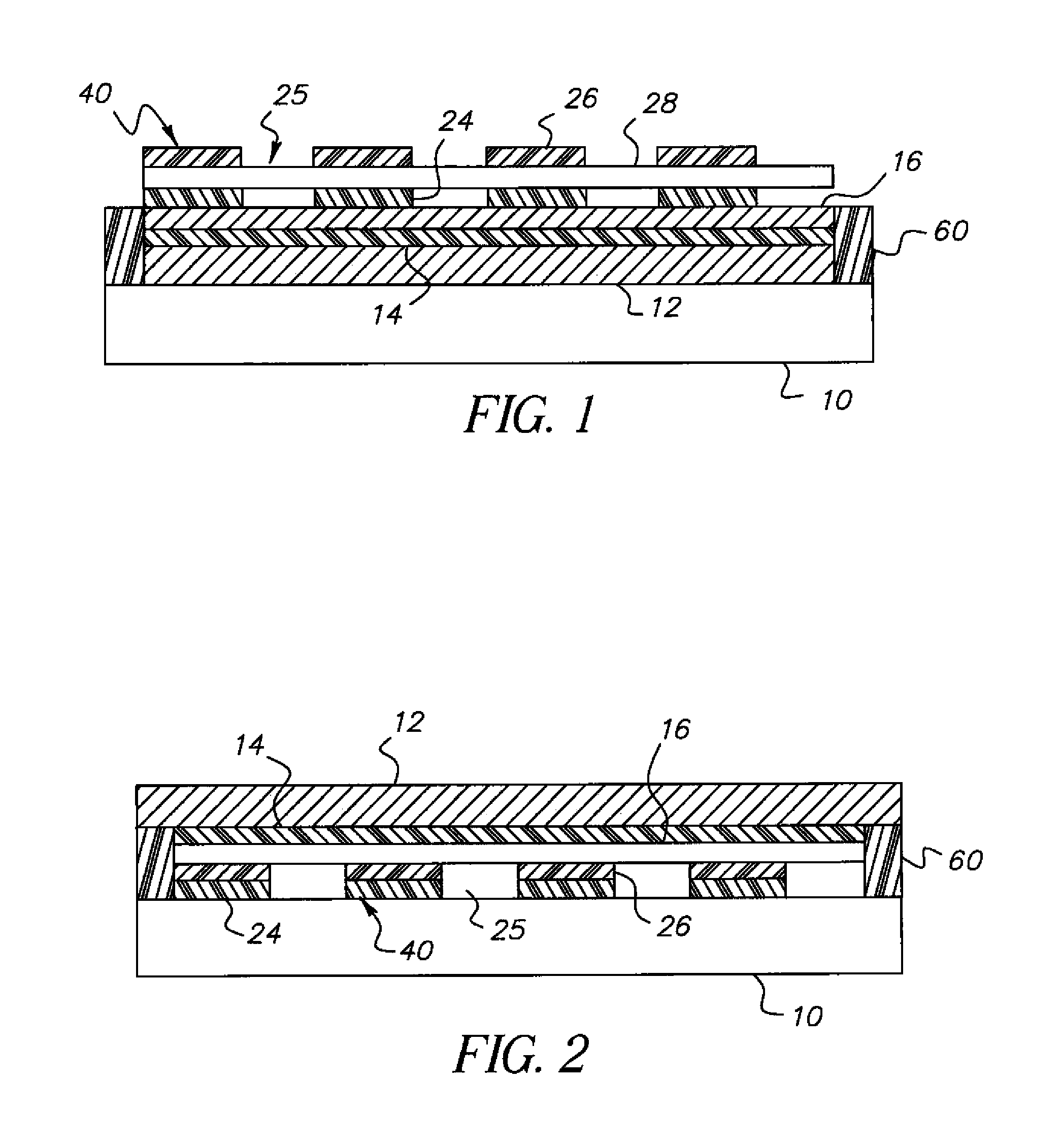
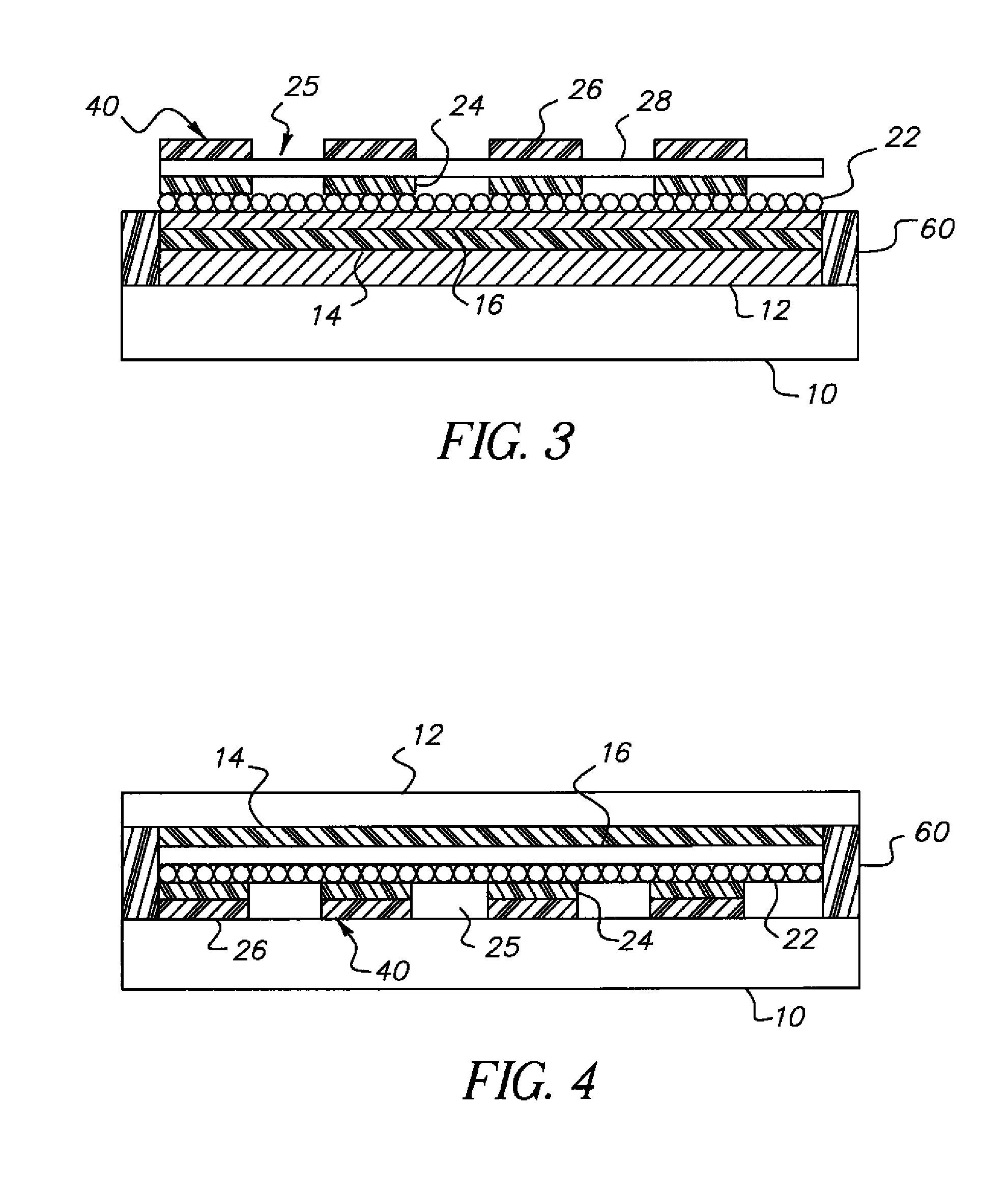
[0025]Referring to FIG. 1, in one embodiment of the present invention, an organic light-emitting diode OLED device comprises a first electrode 12 and a second transparent electrode 16 having one or more organic layers 14 formed there-between, at least one organic layer being light-emitting; and a contrast enhancement element 40 formed on a side of the second transparent electrode 16 opposite the organic layers 14, wherein the contrast enhancement element 40 comprises a patterned reflective layer 24 for reflecting emitted light and a corresponding light-absorbing layer 26 for absorbing ambient light, wherein the reflective layer 24 is located between the light-absorbing layer 26 and the second transparent electrode 16 and wherein the corresponding layers form one or more transparent openings 25 through the reflective and light-absorbing layers 24 and 26 so that light emitted by the light-emitting organic layers 14 passes through the transparent openings 25. Due to the presence of the...


PUM


Abstract

An organic light-emitting diode (OLED) device, comprises: a first electrode and a second transparent electrode having one or more organic layers formed there-between, at least one organic layer being light-emitting; and a contrast enhancement element formed on a side of the second transparent electrode opposite the organic layers, wherein the contrast enhancement element comprises a patterned reflective layer for reflecting emitted light and a corresponding light-absorbing layer for absorbing ambient light, wherein the reflective layer is located between the light-absorbing layer and the second transparent electrode and wherein the corresponding layers form one or more transparent openings through the reflective and light-absorbing layers so that light emitted by the light-emitting organic layer passes through the transparent openings.

Description

FIELD OF THE INVENTION[0001]The present invention relates to organic light-emitting diode (OLED) devices, and more particularly, to OLED device structures for improving light output and contrast.BACKGROUND OF THE INVENTION[0002]Organic light-emitting diodes (OLEDs) are a promising technology for flat-panel displays and area illumination lamps and backlights. However, OLED devices typically have a highly reflective back electrode to enhance the output of emitted light through one side of the OLED device. This highly reflective back electrode also reflects ambient light, thereby reducing the ambient contrast ratio of the OLED device. As is known in the prior art, circular polarizers can greatly reduce the reflected ambient light, but such circular polarizers are expensive.[0003]Significant portions of emitted light may also be trapped in OLED devices. Scattering layers may be employed to improve the light emission of OLED devices, but may inhibit the effectiveness of circular polarize...

Claims


Application Information

Patent Timeline
Patent Type & Authority Patents(United States)
IPC IPC(8): H01J1/62
CPCH01L27/322H01L51/5284H01L51/5268H01L2251/5315H10K59/38H10K50/854H10K50/865H10K2102/3026
Inventor COK, RONALD S.
Owner GLOBAL OLED TECH
Why Eureka
Try Eureka