
Pressure trip device for circuit breaker

a circuit breaker and pressure trip technology, applied in the direction of circuit-breaking switches, circuit-breaking switches for excess current, protection switches, etc., can solve the problems of circuit breaker and drastic increase in arc energy, and achieve the effect of shortening the time for tripping

Active Publication Date: 2008-07-22
LG IND SYST CO LTD
View PDF12 Cites 6 Cited by
  • Summary
  • Abstract
  • Description
  • Claims
  • Application Information

AI Technical Summary

Benefits of technology

"The present invention provides a pressure trip device for a circuit breaker that can quickly trip the breaker in case of an electric shortage current. The device includes a plurality of single pole switching units, a switching mechanism, a trip bar, a gas pressure shooter, and a protrusion wall portion. The gas pressure shooter is perpendicularly movable and connected to the arc gas exhaust port, allowing for quicker tripping of the circuit breaker. The technical effect of this invention is to improve the speed and reliability of circuit breaker tripping in case of an electric shortage current."

Problems solved by technology

However, the conventional circuit breaker has the following problems.
Since the conventional circuit breaker is tripped by a process using mechanisms of a multi-step, arc energy is drastically increased due to a time delay at the time of an occurrence of an electric shortage current.

Method used


Image

  • Pressure trip device for circuit breaker
  • Pressure trip device for circuit breaker
  • Pressure trip device for circuit breaker

Examples


Embodiment Construction

[0032]Reference will now be made in detail to the preferred embodiments of the present invention, examples of which are illustrated in the accompanying drawings.

[0033]Hereinafter, a pressure trip device for a circuit breaker according to a first embodiment of the present invention will be explained in more detail with reference to the attached drawings.

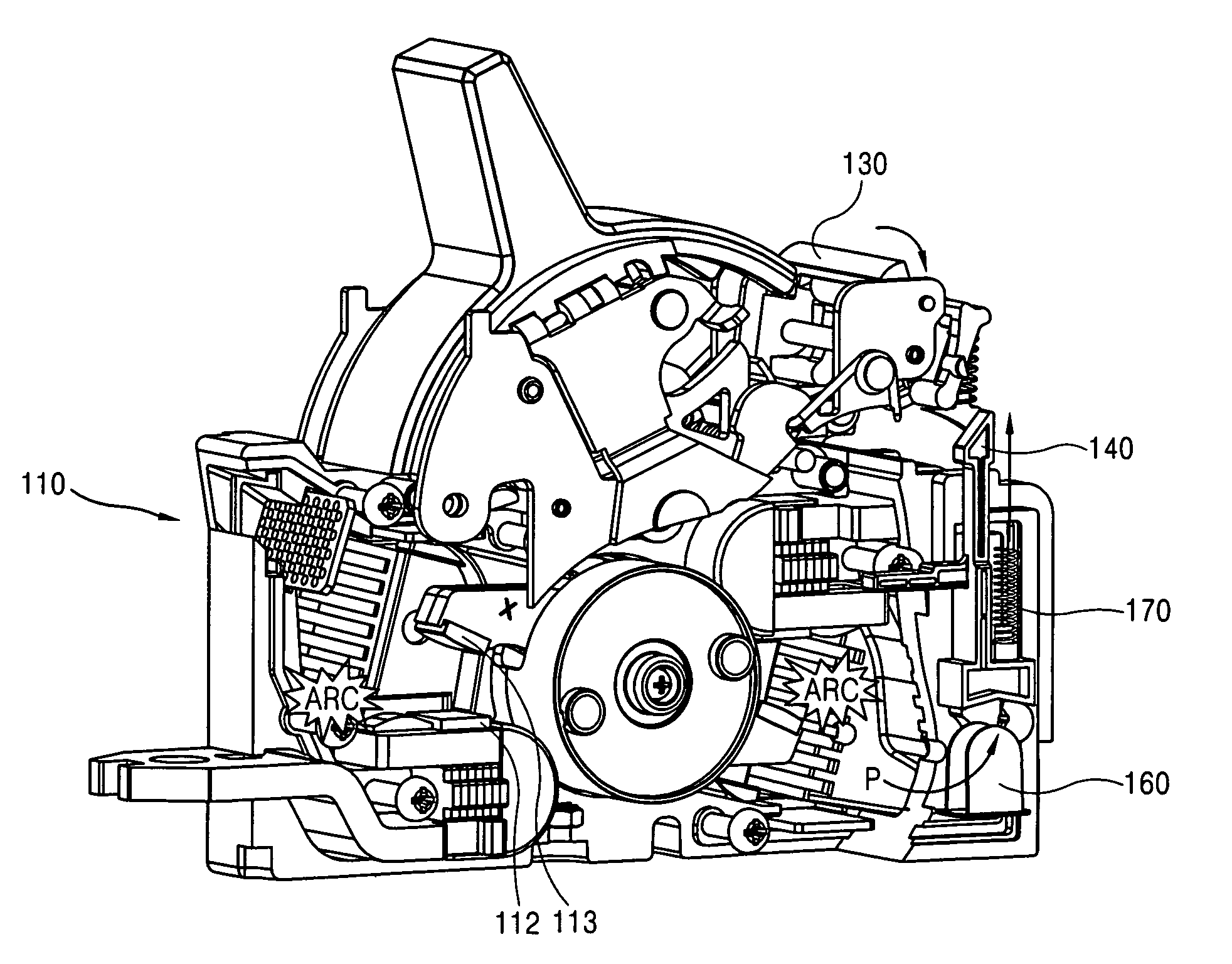
[0034]Referring to FIG. 7, a pressure trip device for a circuit breaker according to a first embodiment of the present invention trips a circuit breaker by using a pressure of arc gas generated between a movable contactor 113 of FIG. 11 and a fixed contactor 112 of the circuit breaker of FIG. 11 when an abnormal current such as an electric shortage current flows on a circuit.

[0035]A circuit breaker having the pressure trip device according to the first embodiment of the present invention comprises a plurality of single pole switching units according to each phase 110, a switching mechanism 120, a trip bar 130, a gas pressure shooter 1...


PUM


Abstract

A pressure trip device for a circuit breaker comprises a plurality of single pole switching units, each unit corresponding to each electrical phase hermetically mounting movable contactors and fixed contactors in an insulated case in order to switch electrical circuits according to each phase, having arc gas exhaust port, and connected to one another by a shaft; a switching mechanism connected to one of the single pole switching units for contacting or separating the movable contactor of the connected single pole switching unit to / from the fixed contactor of the connected single pole switching unit; a trip bar connected to the switching mechanism for tripping the switching mechanism; a gas pressure shooter facing the trip bar, and perpendicularly movable between a position for rotating the trip bar by a pressurization and a position separated from the trip bar; and a protrusion wall portion having a pair of wall portions facing to each other and perpendicularly extending from at least one outer surface of each case of the single pole switching units, having one wall portion for connecting lower ends of the pair of wall portions to each other, and forming a gas pressure storing space for supporting the gas pressure shooter to be perpendicularly movable and connected to the arc gas exhaust port. Accordingly, the circuit breaker is tripped faster than the conventional one using a tripping process by mechanisms of multi-step.

Description

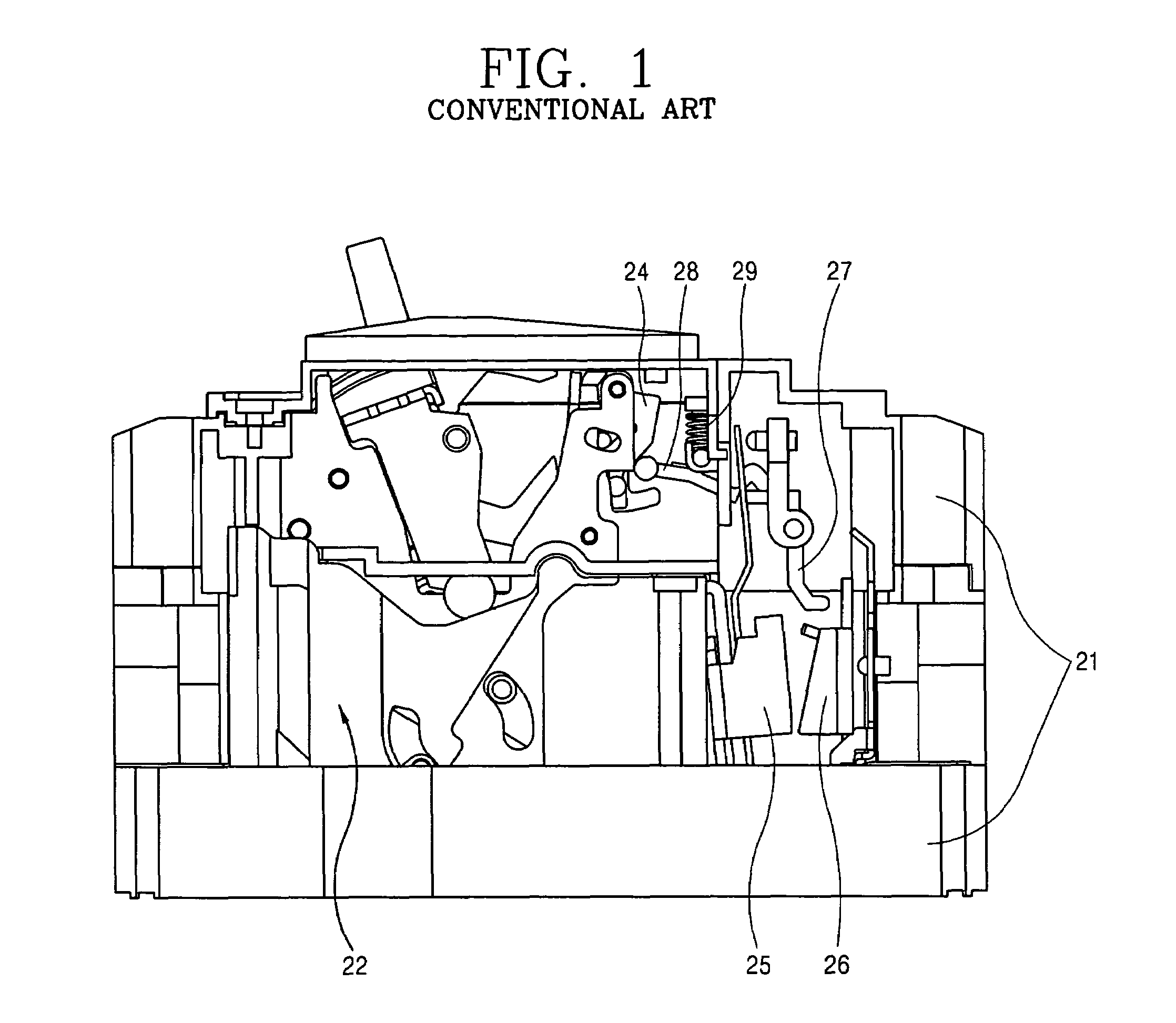
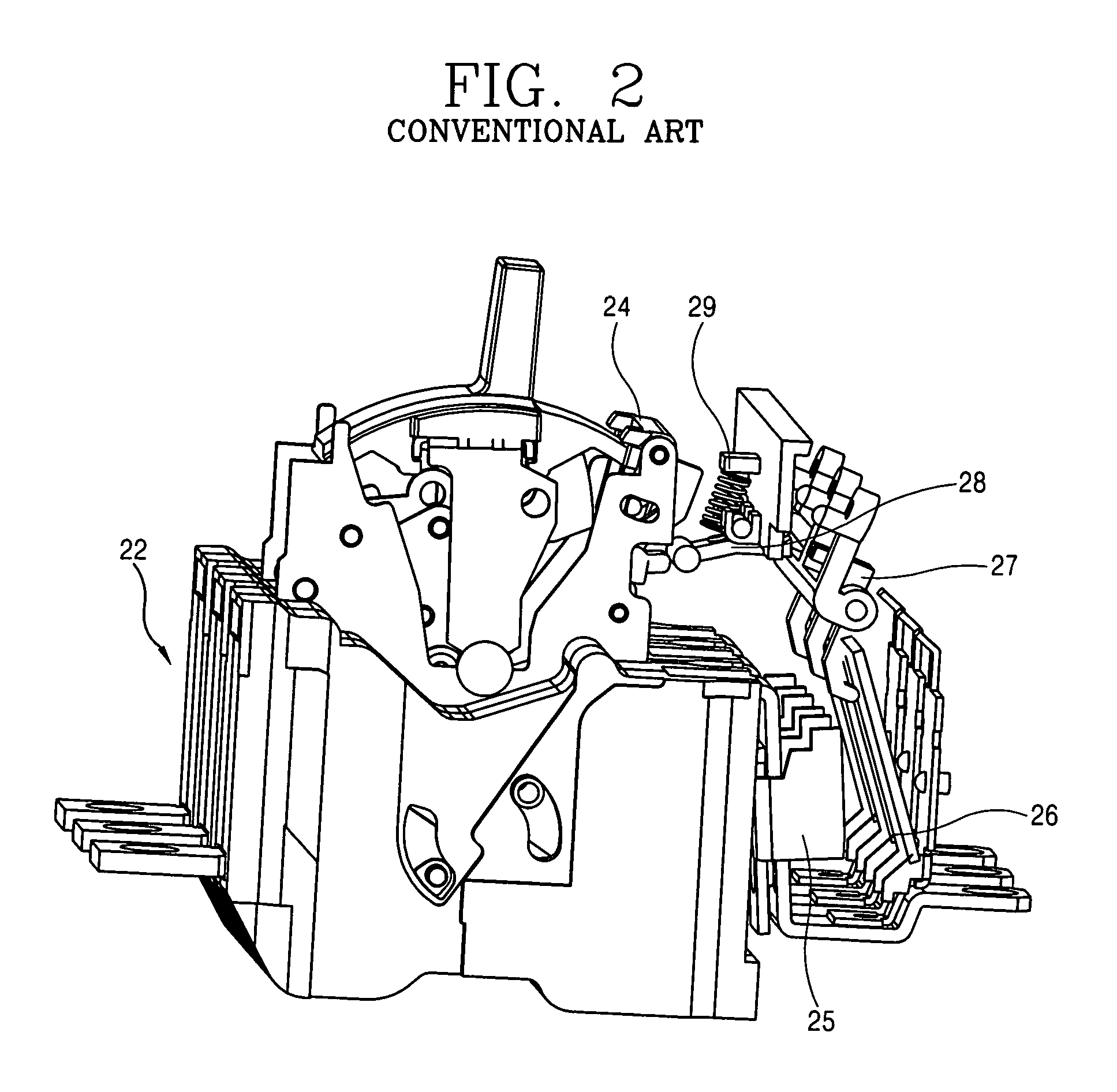
BACKGROUND OF THE INVENTION[0001]1. Field of the Invention[0002]The present invention relates to a circuit breaker, and more particularly, to a pressure trip device for a circuit breaker capable of faster tripping a circuit breaker by using a pressure of arc gas generated when a movable contactor and a fixed contactor are separated from each other by an electromagnetic repulsive force.[0003]2. Description of the Related Art[0004]FIGS. 1 and 2 are respectively a lateral view and a perspective view of a circuit breaker in accordance with the conventional art.[0005]As shown in FIGS. 1 and 2, the conventional circuit breaker constituted with a single pole switching unit 22 comprises an outer case 21 for protecting a mechanism, a magnetic core 25 installed in the outer case 21 for generating an electromagnetic force proportionally to an electrical current flowing on the circuit breaker, an armature 26 attracted by the magnetic core 25, a cross bar 27 actuated by the armature 26, a trip s...

Claims


Application Information

Patent Timeline
Patent Type & Authority Patents(United States)
IPC IPC(8): H01H9/00
CPCH01H77/10H01H2077/025H01H71/10
Inventor OH, KI-HWAN
Owner LG IND SYST CO LTD
Learn More