
Adverse condition detector with diagnostics

a technology of adverse condition and detector, applied in the direction of fire alarm, smoke/gas actuation, instruments, etc., can solve the problems of detector not being interrogated by field service personnel or at the manufacturing facility after the incident, and the detecting device includes little to no historical data

Active Publication Date: 2008-07-22
WALTER KIDDE PORTABLE EQUIP
View PDF13 Cites 65 Cited by
  • Summary
  • Abstract
  • Description
  • Claims
  • Application Information

AI Technical Summary

Problems solved by technology

In the current available adverse condition detecting devices, the detecting device includes little to no capacity to record historical data as to how the detector is operating.
However, the detector cannot be interrogated by field service personnel or at the manufacturing facility after a product recall to determine additional information regarding the operation of the detector.

Method used


Image

  • Adverse condition detector with diagnostics
  • Adverse condition detector with diagnostics
  • Adverse condition detector with diagnostics

Examples


Embodiment Construction

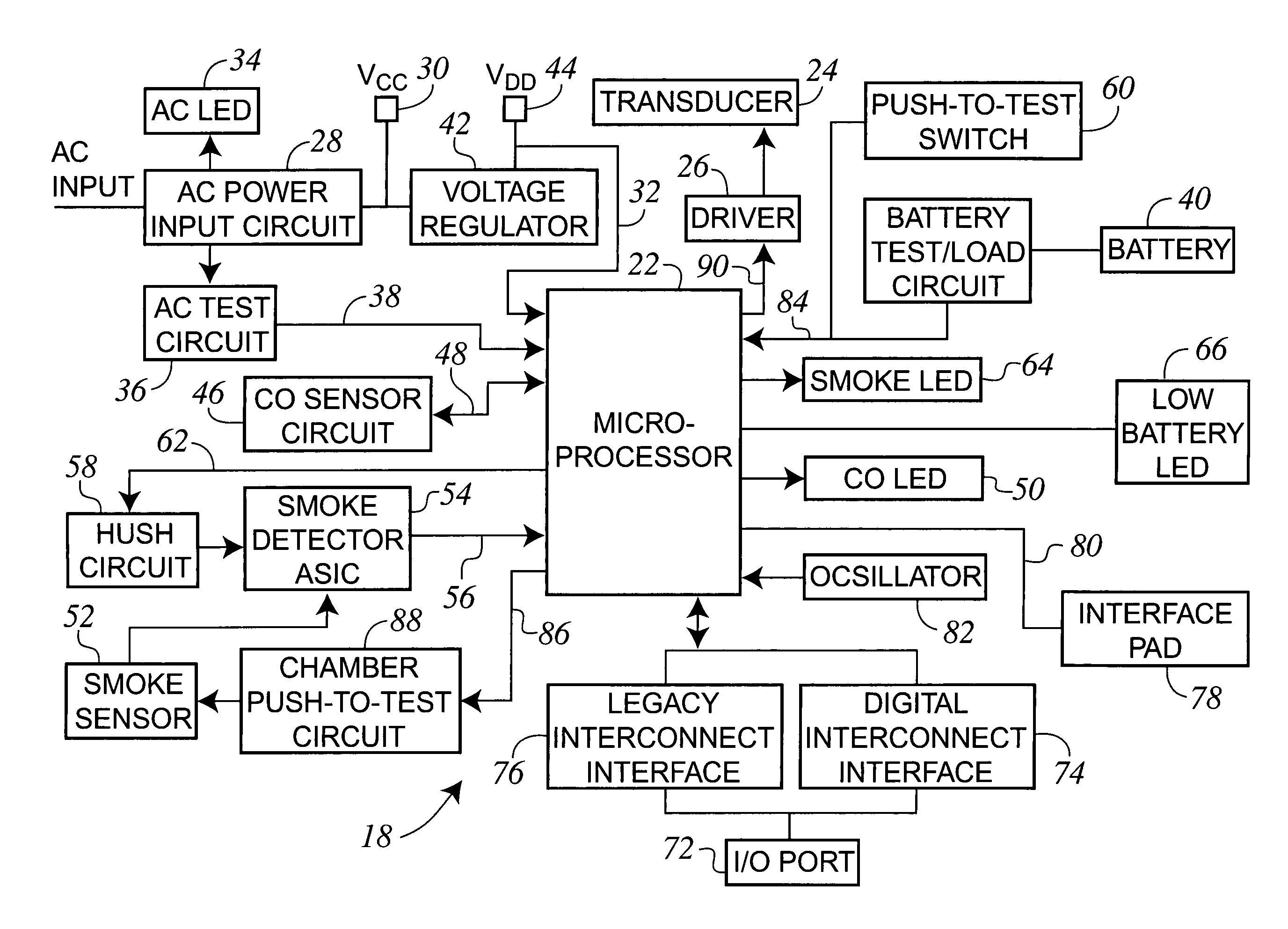
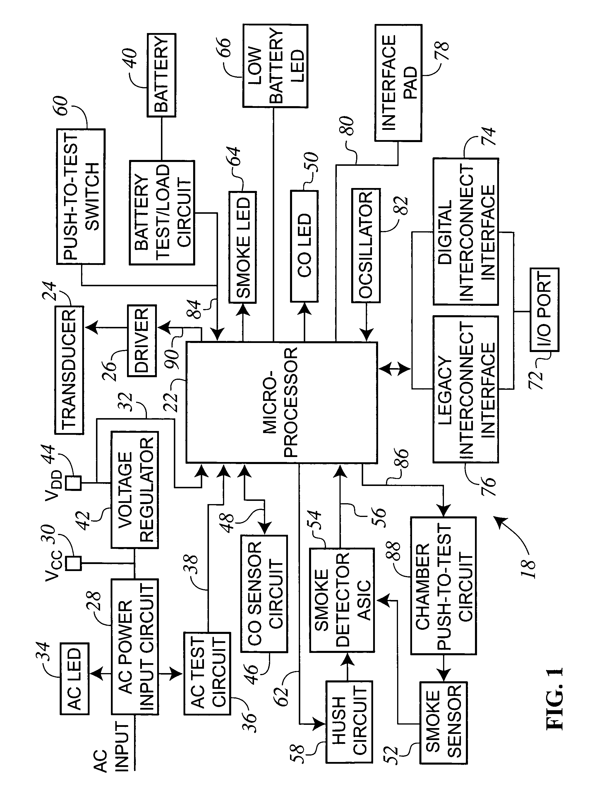
[0017]Referring now to FIG. 1, thereshown is a block diagram of an adverse condition detector 18 of the present invention. As described, the adverse condition detector 18 of the present invention is a combination smoke and CO detector.

[0018]The adverse condition detector 18 includes a central microprocessor 22 that controls the operation of the adverse condition detector 18. In the preferred embodiment of the invention, the microprocessor 22 is available from Atmel Mega 32, although other microprocessors could be utilized while operating within the scope of the present invention. The block diagram of FIG. 1 is shown on an overall schematic scale only, since the actual circuit components for the individual blocks of the diagram are well known to those skilled in the art and form no part of the present invention.

[0019]As illustrated in FIG. 1, the adverse condition detector 18 includes an alarm indicator or transducer 24 for alerting a user that an adverse condition has been detected....


PUM


Abstract

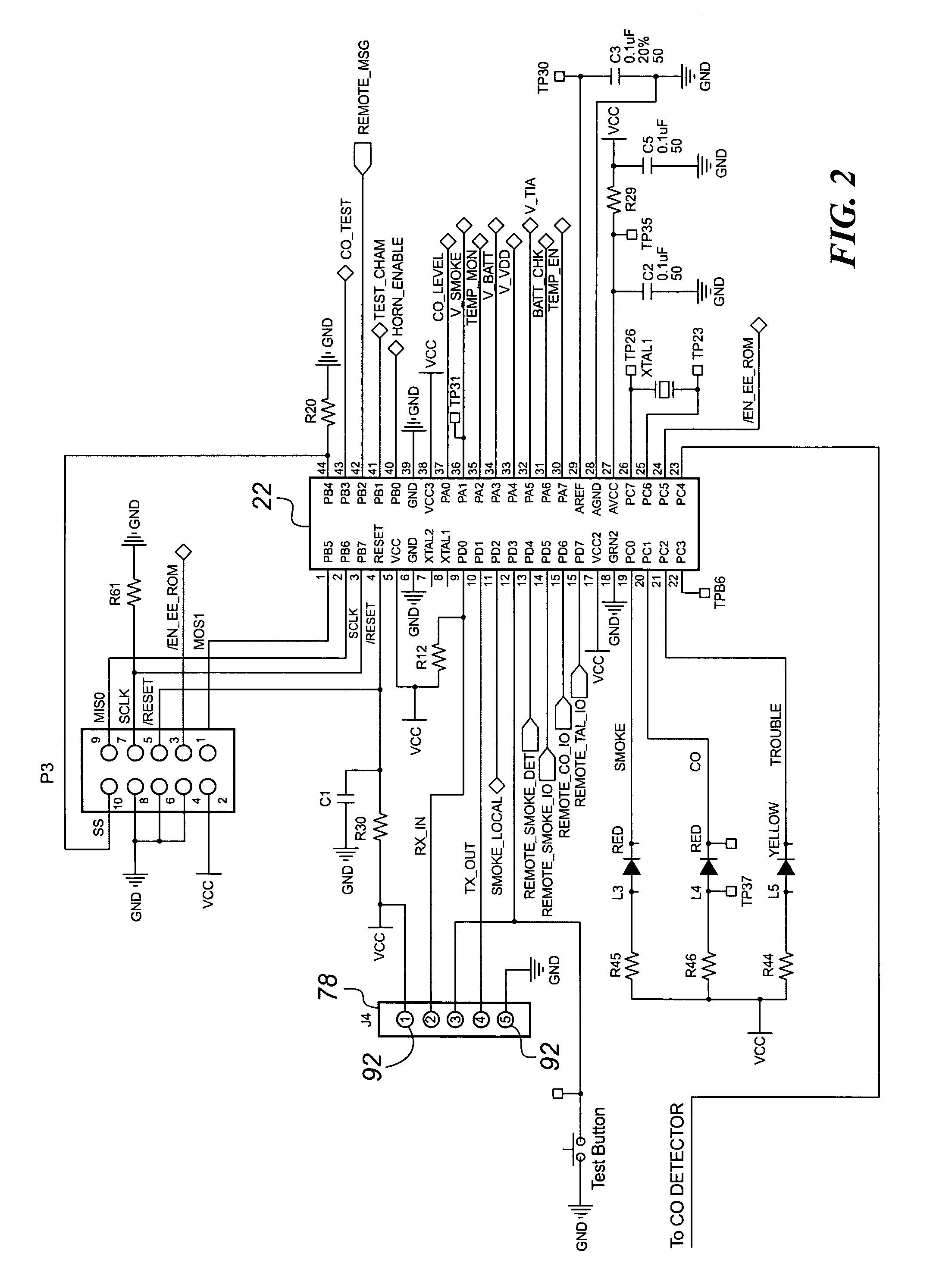
An adverse condition detector that records historical data concerning the operation of the detector such that the detector can be interrogated by a technician. The microprocessor of the adverse condition detector monitors for alarm conditions and other important information related to the operation of the detector. Upon identifying an important characteristic of the detector operation, the microprocessor time stamps the information and stores the information within memory of the microprocessor. The detector includes an interface pad that is accessible from the exterior of the detector such that a technician can access the interface pad without removing the detector housing.

Description

CROSS REFERENCE TO RELATED APPLICATION(S)[0001]The present application is based on and claims priority to U.S. Provisional Patent Application Ser. No. 60 / 653,808 filed on Feb. 17, 2005.BACKGROUND OF THE INVENTION[0002]The present invention generally relates to adverse condition detectors, such as smoke detectors, carbon monoxide detectors and combination units. More specifically, the present invention relates to an adverse condition detector that includes the ability to store historical information regarding the alarms generated based on the adverse condition detected and other information regarding the operation of the detector.[0003]Currently available adverse condition detectors, such as carbon monoxide alarms for residential homes, detect a level of carbon monoxide in the area surrounding the alarm device and operate a transducer, such as an audible horn, to indicate to the home occupant that a hazardous level of carbon monoxide has been detected. Similar detectors are available...

Claims


Application Information

Patent Timeline
Patent Type & Authority Patents(United States)
IPC IPC(8): G08B17/10
CPCG08B29/043G08B26/002G08B17/113G08B17/10G08B31/00
Inventor SCUKA, RODNEY W.KAISER, TIMOTHY D.BAKER, PAUL J.
Owner WALTER KIDDE PORTABLE EQUIP
Learn More