Clear channel assessment in wireless communications

a wireless communication and clear channel technology, applied in the field of wireless communications, can solve the problems of low effective data throughput, transmission delay, and low accuracy of known techniques

Active Publication Date: 2008-07-22
NXP USA INC
View PDF6 Cites 41 Cited by
  • Summary
  • Abstract
  • Description
  • Claims
  • Application Information

AI Technical Summary

Benefits of technology

[0016]To address these and other perceived shortcomings and desires, the present invention is directed in part to a packet detection unit and signal recognition method that includes at least one of relative energy detection operable on assessment of a relative energy threshold for an inbound signal borne across an RF channel, carrier sense operable upon on assessment of at least one of a peak-to-sidelobe ratio and peak-to-peak distance defined by the inbound signal, and comparison operable upon demodulated data corresponding to the inbound signal as compared to predetermined preamble data. Clear channel assessment is performed based on determinations undertaken by one or more of the aforementioned relative energy detection, carrier sense and comparison operations.

Problems solved by technology

Inbound signals in the tuned or operating RF channel which do not meet these CCA guidelines are considered to bear either corrupted frames, or represent interference or noise in the channel.
Thus, the presence of strong interference in the operating channel, will cause (in the case of a CCA mode 1 implementation) or potentially may (in the case of a CCA mode 3 or 5) cause a false busy to be reported, and thus prevent the transceiver from transmitting, which may in turn cause transmission delay and lower effective data throughput.
However, known techniques are relatively complex and are thus power inefficient and expensive to implement.
Finally, while the defined 802.11 / 802.11b CCA modes account accommodate a range of operational environments, they are not appropriate for every environment and channel condition.

Method used


Image

  • Clear channel assessment in wireless communications
  • Clear channel assessment in wireless communications
  • Clear channel assessment in wireless communications

Examples


Embodiment Construction

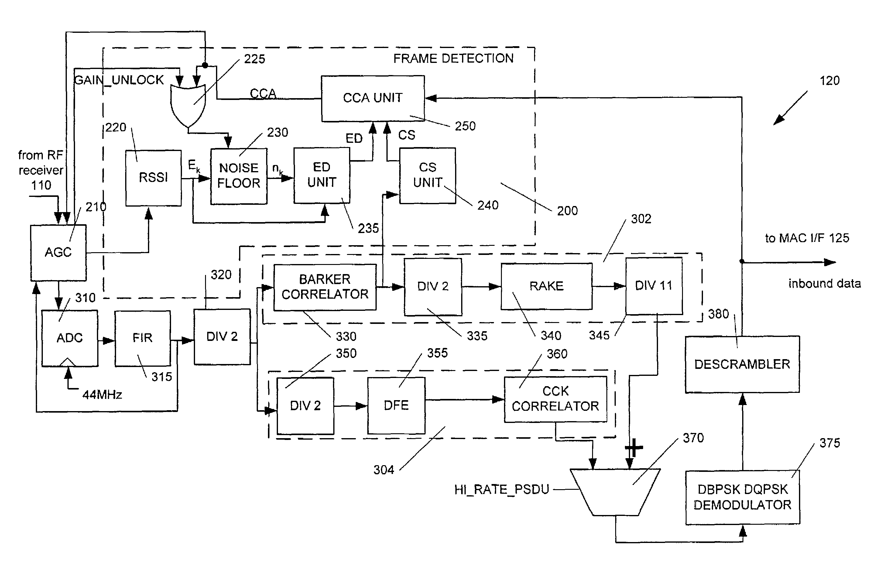
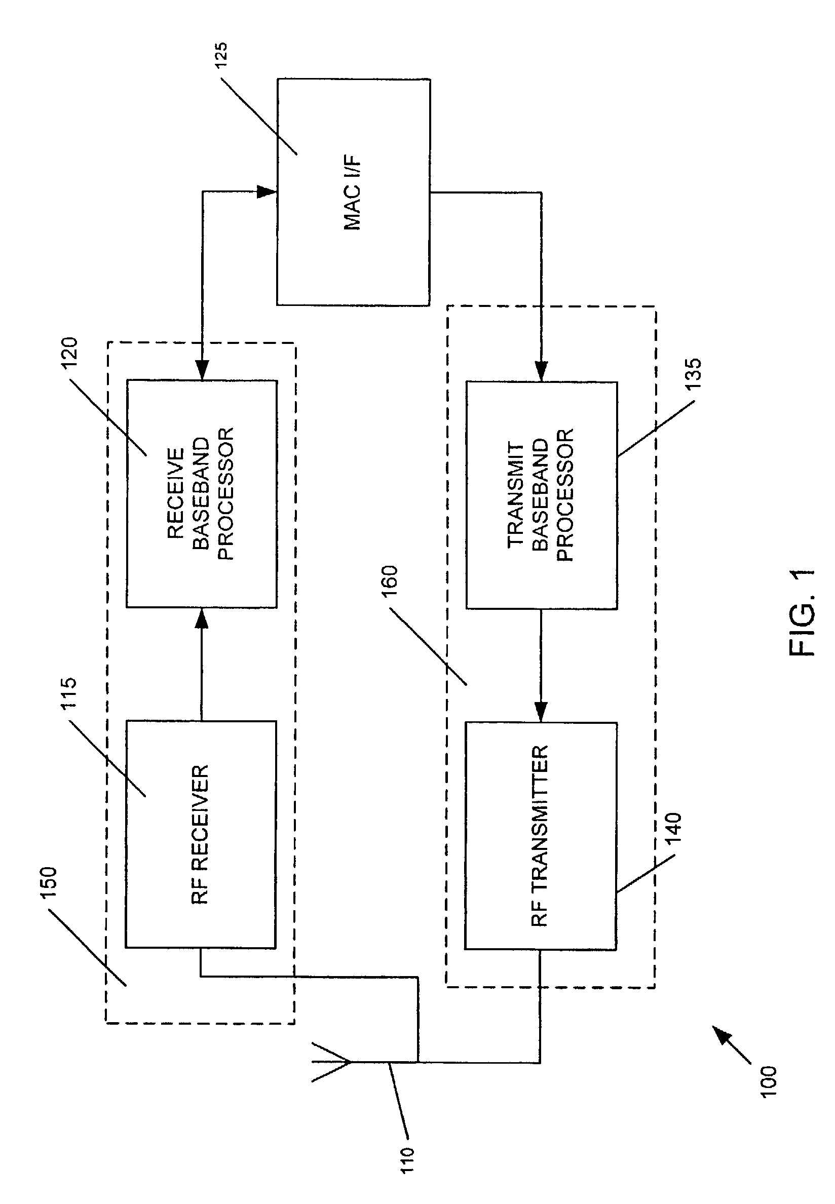
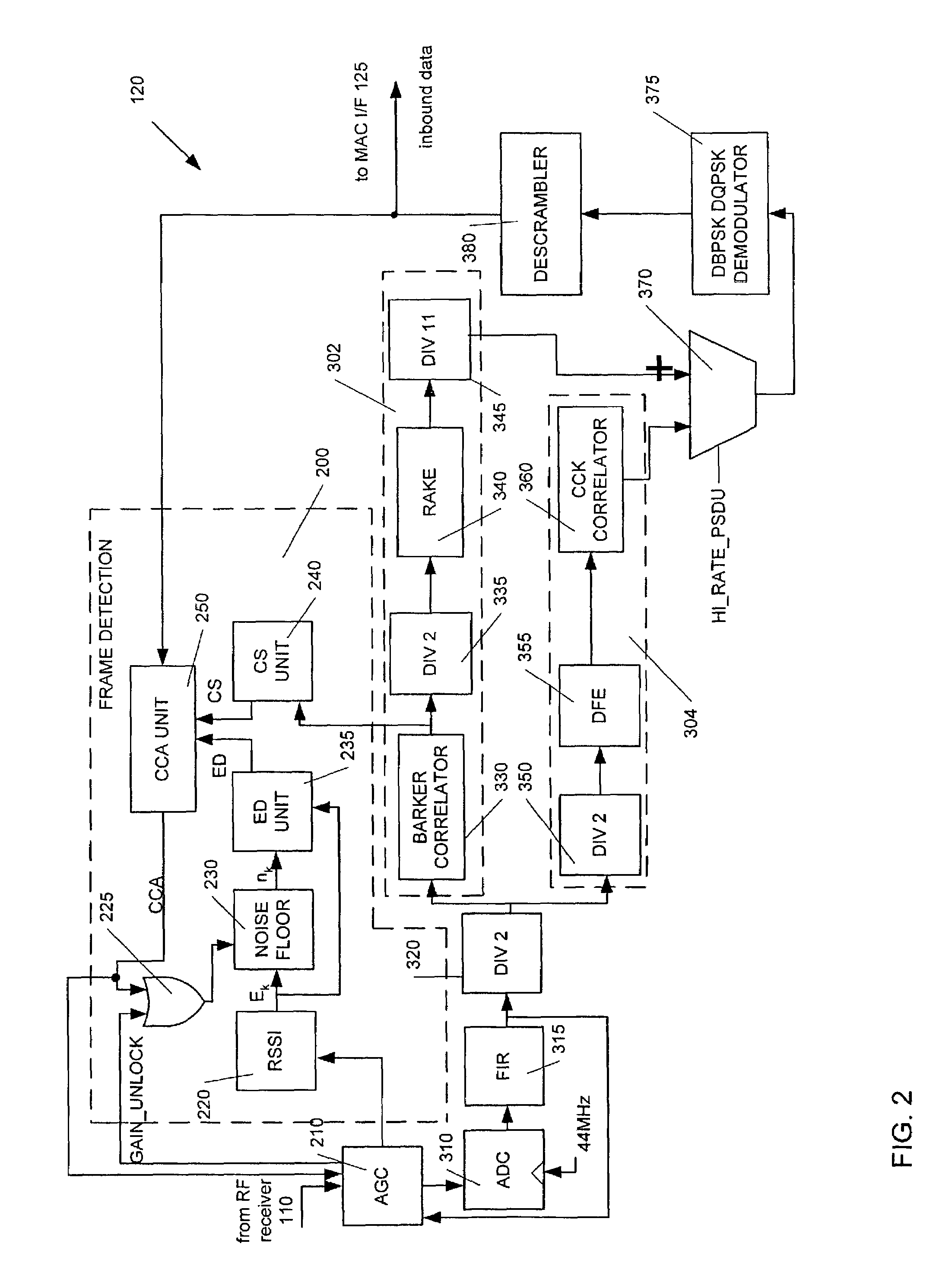
[0029]Turning now to the figures, FIG. 1 illustrates a wireless communications transceiver 100 according to an embodiment of the invention. In this embodiment, inbound RF signals potentially conveying an 802.11 or 802.11b compliant PLCP frame are picked up by the duplex antenna 10 and routed to the RF receiver unit 115 of a receiver 150 arranged in a manner consistent with the present invention. The RF receiver unit 115 performs routine downconversion and automatic gain control of the inbound RF signals, and presents an analog baseband signal containing the aforementioned 802.11b PLCP frame to the receive baseband processor 120. The functions of the receive baseband processor 120 will be detailed below with reference to FIG. 2, including packet detection and channel busy consistent with the present invention, along with conventional symbol correlation and / or demodulation of the preamble, header and payload portions of each inbound 802.11b PLCP frame to recover bitstream data for rec...


PUM


Abstract

Techniques for and apparatus capable of implementing packet detection and signal recognition in wireless communications systems are disclosed. In particular, the disclosed techniques and apparatus incorporate at least one of relative energy detection operable on assessment of a relative energy threshold for an inbound signal borne across an RF channel, carrier sense operable upon on assessment of at least one of a peak-to-sidelobe ratio and peak-to-peak distance defined by the inbound signal, and comparison operable upon demodulated data corresponding to the inbound signal as compared to predetermined preamble data. Clear channel assessment is performed based on determinations undertaken by one or more of the aforementioned relative energy detection, carrier sense and comparison operations.

Description

TECHNICAL FIELD[0001]The present invention generally relates to wireless communications, and is specifically concerned with clear channel assessment techniques to determine the presence or absence of a valid inbound signal.BACKGROUND OF THE INVENTION[0002]The past few years has witnessed the ever-increasing availability of relatively cheap, low power wireless data communication services, networks and devices, promising near wire speed transmission and reliability. One technology in particular, described in the IEEE Standard 802.11b-1999 Supplement to the ANSI / IEEE Standard 802.11, 1999 edition, collectively incorporated herein fully by reference, and more commonly referred to as “802.11b” or “WiFi”, has become the darling of the information technology industry and computer enthusiasts alike as a wired LAN / WAN alternative because of its potential 11 Mbps effective throughput, ease of installation and use, and transceiver component costs make it a real and convenient alternative to wi...

Claims


Application Information

Patent Timeline
Patent Type & Authority Patents(United States)
IPC IPC(8): H04L12/413H04L12/28
CPCH04W24/00H04W74/08H04B1/707H04B17/00
Inventor TANG, HSIAO-CHENGHSU, YUNGPINGHU, GUORONGFENG, WEISHI
Owner NXP USA INC
Why Eureka
Try Eureka