
Technique for switching between input clocks in a phase-locked loop

a phase-locked loop and input clock technology, applied in the direction of electrical equipment, pulse automatic control, etc., can solve the problems of low-bandwidth plls suitable for meeting tight phase transient requirements, difficult to implement with discrete components, and introduce transmission errors or other problems, so as to reduce or eliminate phase glitches, the effect of being ready to implemen

Active Publication Date: 2008-07-29
SKYWORKS SOLUTIONS INC
View PDF10 Cites 40 Cited by
  • Summary
  • Abstract
  • Description
  • Claims
  • Application Information

AI Technical Summary

Benefits of technology

[0006]A technique that is readily implemented in monolithic integrated circuits reduces or eliminates phase glitches in a phase-locked loop (PLL) output when switching between input reference clock signals. The technique combines a pulsed phase-difference signal and a pulsed phase-difference compensation signal to substantially attenuate a DC component of the phase-difference signal and at least partially attenuate harmonic components of the phase-difference signal. The pulsed phase-difference compensation signal is based on an indicator of a phase difference between the input reference clock signals.

Problems solved by technology

Such phase changes in the output clock can introduce transmission errors or other problems.
However, low-bandwidth PLLs suitable for meeting tight phase transient requirements may be difficult to implement in a monolithic integrated circuit and may be expensive or difficult to implement with discrete components.
In addition, low-bandwidth PLLs typically achieve lock relatively slowly and typically generate output clocks having increased jitter due to reduced filtering of the output of a voltage-controlled oscillator (VCO) included in the PLL.

Method used


Image

  • Technique for switching between input clocks in a phase-locked loop
  • Technique for switching between input clocks in a phase-locked loop
  • Technique for switching between input clocks in a phase-locked loop

Examples


Embodiment Construction

)

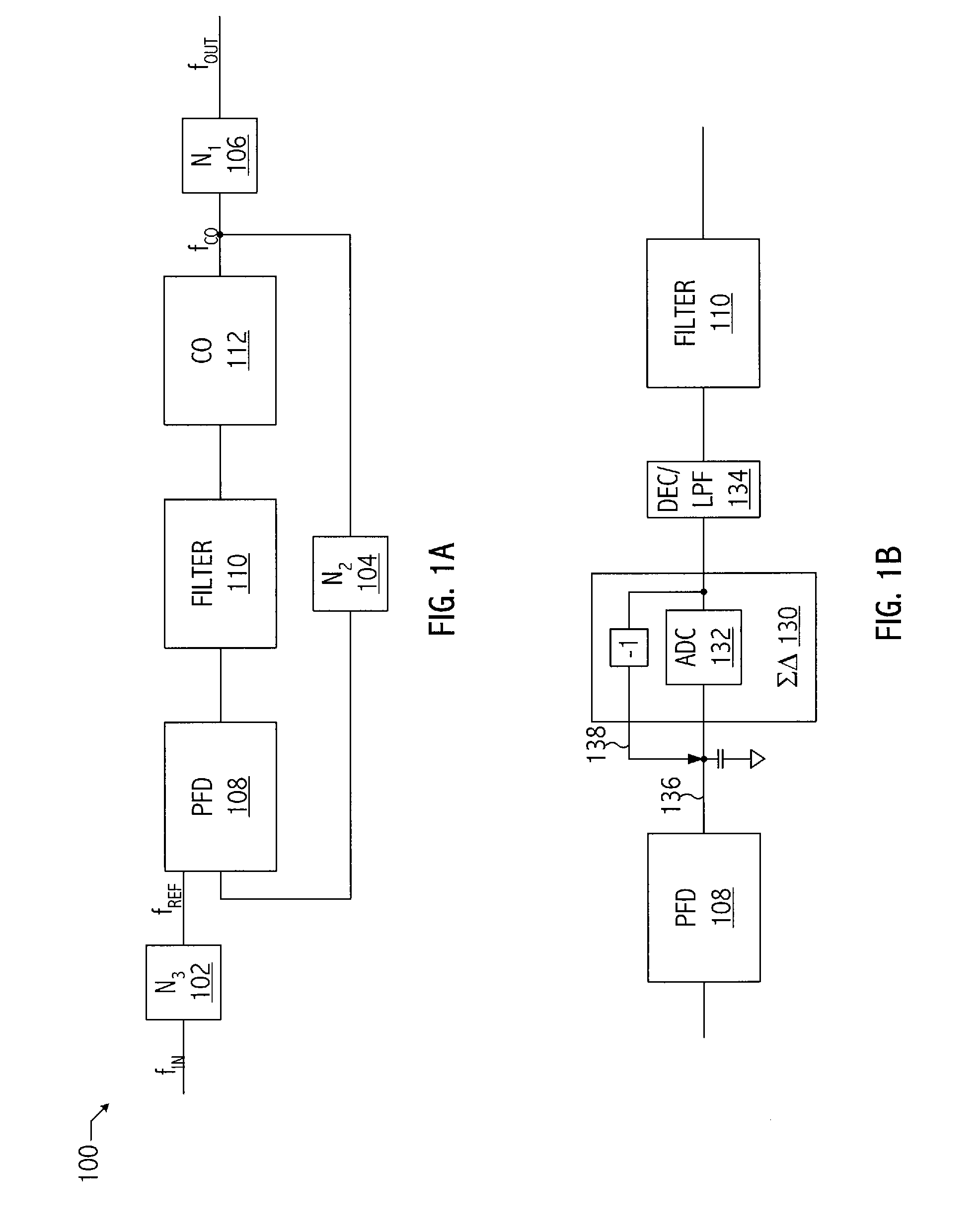
[0026]Referring to FIG. 1A, a phase-locked loop (i.e., PLL) has a programmable bandwidth (i.e., f3dB) and a programmable reference frequency (i.e., fREF). In at least one embodiment of PLL 100, the bandwidth of PLL 100 may be quantified as follows:

[0027]f3⁢dB=(fREFd×2p)×cf⁡(N2,p),

where p is an index value, e.g., 0, 1, 2, . . . , 11, and

[0028]fREF=fINN3=fCON2.

The variable Cf(N2, p) is a correction factor that is based on the value of feedback divider 104 (i.e., N2) and the index value p. A value of p corresponds to a particular f3dB associated with a particular fREF, as illustrated in FIG. 10A. The variable d is based on the index value p and is a factor that adjusts for implementing a continuous time system using a discrete time PLL. In at least one embodiment of PLL 100, a user provides a particular value of p and a particular fREF, which correspond to a particular fREF and f3dB pair. The values of fREF and p are used to determine various parameters that are used to configure PLL ...


PUM


Abstract

A technique that is readily implemented in monolithic integrated circuits reduces or eliminates phase glitches when switching between input reference clock signals. The technique combines a pulsed phase-difference signal and a pulsed phase-difference compensation signal to substantially attenuate a DC component of the phase-difference signal and at least partially attenuate harmonic components of the phase-difference signal. The pulsed phase-difference compensation signal is based on an indicator of a phase difference between the input reference clock signals.

Description

BACKGROUND[0001]1. Field of the Invention[0002]This invention relates to phase-locked loops, and more particularly to phase-locked loops with selectable input clock signals.[0003]2. Description of the Related Art[0004]In optical communication systems, line cards compliant with standards such as Synchronous Optical Network (SONET) or Synchronous Digital Hierarchy (SDH) (the European counterpart to SONET) utilize clock generation circuits to generate clocks used in data transmission and reception. In such clock generation circuits, a phase-locked loop (PLL) receives an input reference clock and generates one or more high-speed clocks suitable for use in transmitting or receiving data in a SONET or SDH based system. According to one aspect of those communication systems, multiple reference clocks may be supplied to a clock generation circuit to provide a variety of capabilities, including redundancy. When the PLL in the clock generation circuit switches from using one input reference c...

Claims


Application Information

Patent Timeline
Patent Type & Authority Patents(United States)
IPC IPC(8): H03L7/00
CPCH03L7/087H03L7/18H03L7/093H03L7/0898
Inventor HULFACHOR, RONALD B.SEETHAMRAJU, SRISAI R.CHITNIS, SHAILESH
Owner SKYWORKS SOLUTIONS INC
Learn More