Method and system to calculate a demand for energy

a technology of energy demand and method, applied in the direction of mechanical power/torque control, program control, electric devices, etc., can solve the problems of increasing the cost of energy generation, increasing the difficulty of installing new large-scale distribution, transmission and/or generation capacity, and increasing the difficulty of investment in a de-regulated and/or fast-changing mark

Inactive Publication Date: 2008-07-29
HITACHI ENERGY SWITZERLAND AG
View PDF14 Cites 159 Cited by
  • Summary
  • Abstract
  • Description
  • Claims
  • Application Information

AI Technical Summary

Benefits of technology

[0037]The main advantage of the invention is that management of energy demand, and in particular electrical power demand in an electrical power system may be calculated in a systematic way by power supply companies or power sales companies. The calculations may include instantaneous consumption, accumulated consumption, estimated future consumption, and estimated future consumption with known consumer price sensitivity margins. In line with common practice, time series may be used for calculating demand and demand forecasts.
[0038]A further advantage is that existing power distribution systems for most types of energy may be simply and economically retrofitted with embodiments of the invention and computer program products according to the invention.

Problems solved by technology

The consumption of energy and especially electricity is increasing worldwide; however, installing new large-scale distribution, transmission and / or generation capacity has become increasingly difficult.
This is due to factors including increased load on the environment in the form of CO2 emissions and to an unwillingness to invest in a de-regulated and / or fast-changing market.
Increased consumption of energy coupled with reduced investment in physical plant, particularly of the traditional energy generation types has contributed to a diminished safety margin between available supply and instantaneous demand.
Calculating energy demand forecasts has consequently become more complicated and fluctuations in consumption harder to predict within tighter margins between capacity and demand.

Method used


Image

  • Method and system to calculate a demand for energy
  • Method and system to calculate a demand for energy
  • Method and system to calculate a demand for energy

Examples


Embodiment Construction

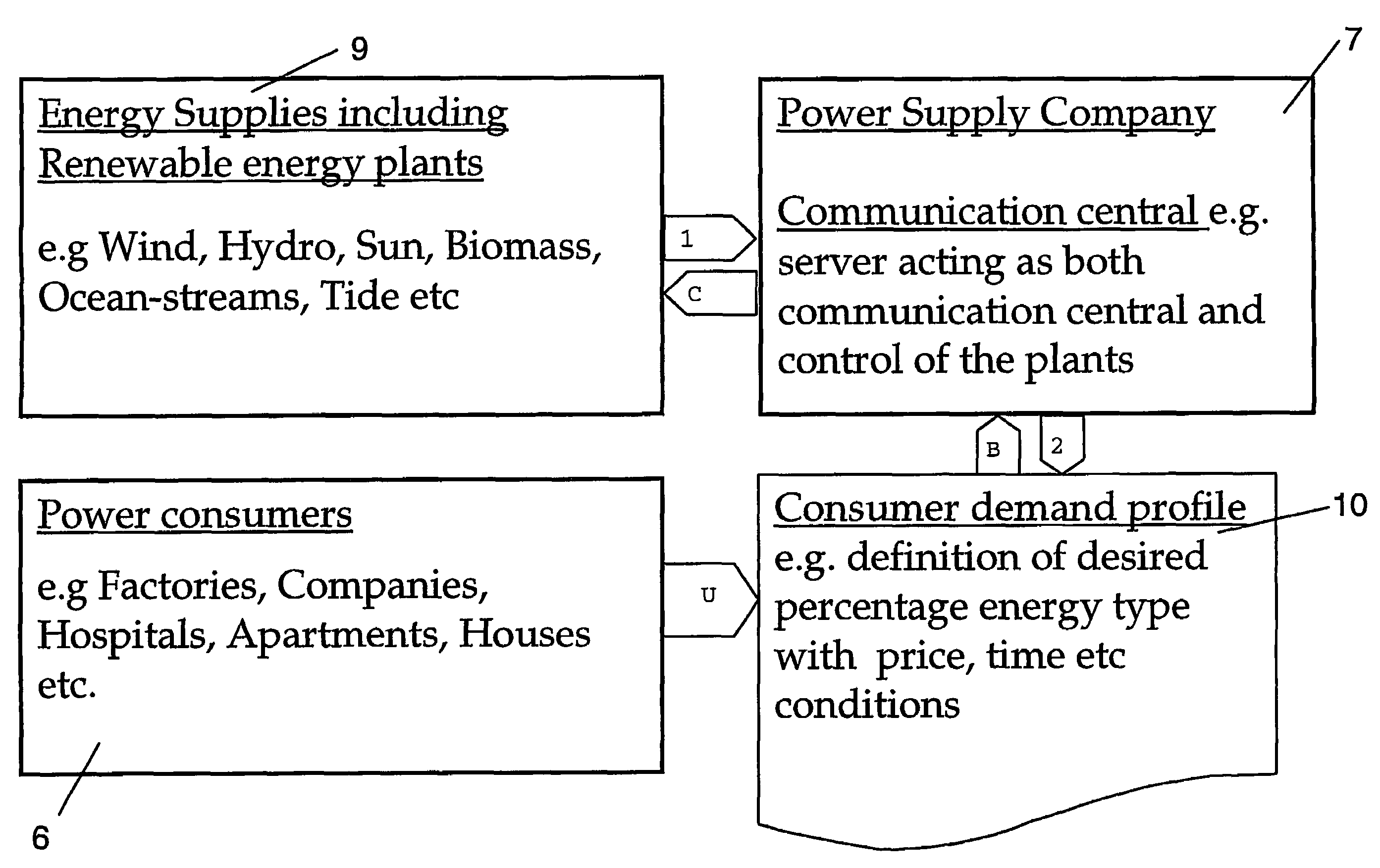
[0046]FIG. 1 shows a simple block diagram showing elements of a system including a consumer demand profile according to an embodiment of the invention. FIG. 1 shows a plurality of power plants 9, including power plants based on renewable energy sources, and a communication system 7 of a Power Supply Company, and a plurality of consumers and power consumers 6 of different types. It is understood that the power consumers are in some way connected to one or more power supply systems so as to receive power sold by the Power Supply Company from one or more of the power plants 9. A customer demand profile 10 is shown.

[0047]The customer demand profile 10 is a document, table or other means provided for each customer. The document is accessible and may be altered at will by each respective customer. Each consumer demand profile for each power consumer is accessible, and readable by the Power Supply Company. The Power Supply Company may also be able to change the available options listed on ...


PUM


Abstract

A method to calculate energy demand in an energy generation, transmission and distribution network including one or more power plants based on different energy source types including renewable energy, a communications system and one or more local consumption metering units. A customer demand profile for one or more customers is provided. A customer-specified proportion of power demand to be supplied from a given energy source type is registered. A total predicted energy demand dependent is calculated in part on an accumulated demand for the given energy source type.

Description

CROSS-REFERENCE TO RELATED APPLICATIONS[0001]This application claims priority to U.S. provisional patent application No. 60 / 318,678 filed 13 Sep. 2001 and is the national phase under 35 U.S.C. § 371 of PCT / SE02 / 01637.TECHNICAL FIELD[0002]The present invention relates to supervision and control of an energy generation, transmission and distribution system. In particular the present invention discloses a system, method and a computer program product for calculating a demand for energy from plants based one or more different energy source types, including electrical energy generated from a renewable energy source.BACKGROUND ART[0003]The consumption of energy and especially electricity is increasing worldwide; however, installing new large-scale distribution, transmission and / or generation capacity has become increasingly difficult. This is due to factors including increased load on the environment in the form of CO2 emissions and to an unwillingness to invest in a de-regulated and / or f...

Claims


Application Information

Patent Timeline
Patent Type & Authority Patents(United States)
IPC IPC(8): G05D99/00G05B11/00G05B15/00G06F17/00G06F19/00G06Q10/00H02J3/00
CPCG06Q10/06G06Q30/02G06Q50/06H02J3/00Y04S10/54H02J2003/003Y04S50/14H02J3/003Y02B70/3225Y04S10/50Y04S20/222
Inventor ANDREN, ANDERSLOFGREN, PETERRISSANEN, MARKKUZHOU, GANG
Owner HITACHI ENERGY SWITZERLAND AG
Why Eureka
Try Eureka