Offshore wind energy system with non-skid feet

a technology of wind energy system and offshore wind, which is applied in the direction of machines/engines, artificial islands, mechanical equipment, etc., can solve the problem of complex obtaining of an approximately equal hub height above the ocean surface in the case of such foundations

Active Publication Date: 2008-08-05
SIEMENS GAMESA RENEWABLE ENERGY SERVICE GMBH
View PDF10 Cites 21 Cited by
  • Summary
  • Abstract
  • Description
  • Claims
  • Application Information

AI Technical Summary

Problems solved by technology

The obtaining of an approximately equal hub height above the ocean surface is complex in the case of such foundations because the length of the tripod or that of the jacket must be adapted in its entirety to the erection site.

Method used


Image

  • Offshore wind energy system with non-skid feet
  • Offshore wind energy system with non-skid feet
  • Offshore wind energy system with non-skid feet

Examples


Embodiment Construction

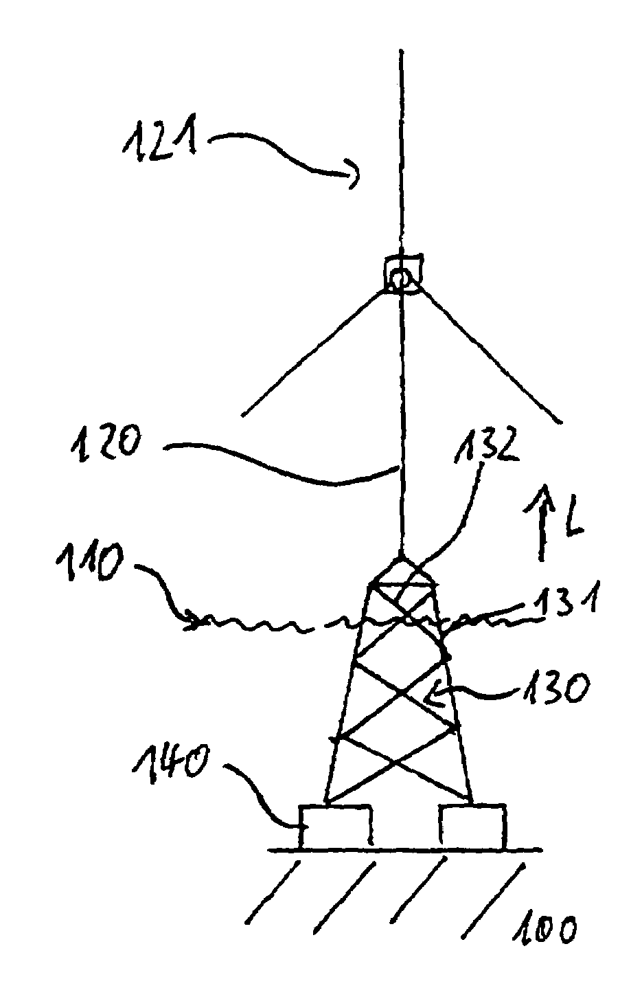
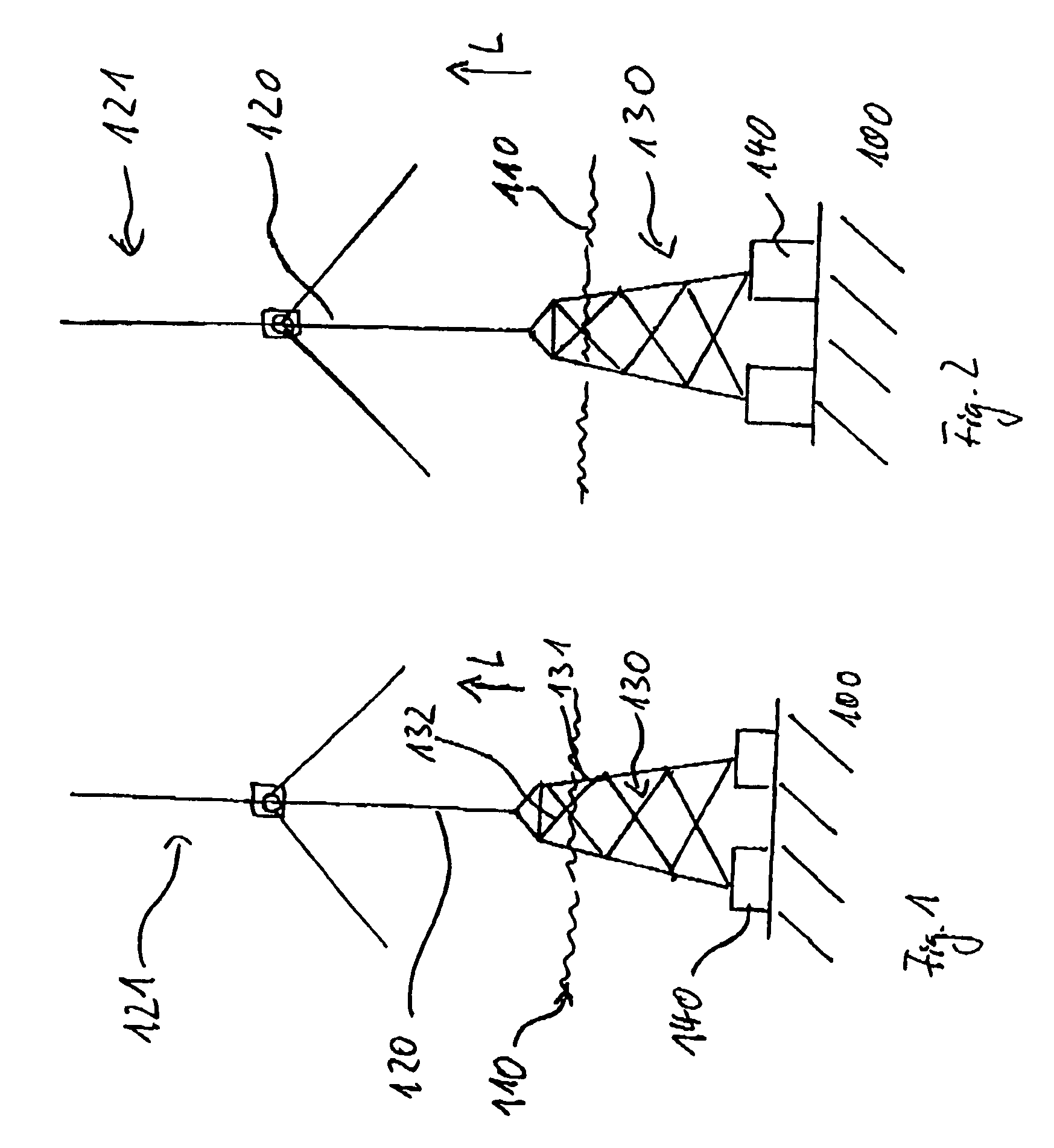
[0016]The wind energy system in accordance with the invention stands with its feet on the ocean bottom, which feet can be adapted in their extension in the longitudinal direction. The longitudinal direction runs along the longitudinal direction of a pipe tower of the wind energy system. Structural components such as, e.g., pipe tower, machine house and carrier structure are preferably standardized and the differing ocean bottom profile and the differing depth of the ocean at the erection side of each foot is compensated by the differing longitudinal extension of the feet in order to obtain a given rotor hub height above the sea level. The leg ends are standardized, preferably the same interval to the ocean surface and the particular clear interval between the leg end and the ocean bottom is filled up by the foot, that compensates this interval in its longitudinal extension. The longitudinal extension of a foot corresponds to the difference between the sum of the height of the rotor ...


PUM


Abstract

This invention entails a wind energy system for offshore use with a longitudinal direction (L) running substantially vertically to an ocean surface in the erected state and with a plurality of feet determined for making contact with the ocean bottom whose extensions in the longitudinal direction (L), especially the depth and / or relief of the ocean bottom, are adapted to a predetermined erection site.

Description

FIELD OF THE INVENTION[0001]The invention relates to a wind energy system for offshore use, to a wind park including two or more of the wind energy systems, and to a method for erecting a wind energy system.BACKGROUND OF THE INVENTION[0002]Wind energy systems are traditionally anchored in offshore use in the form of single-post foundations on the ocean bottom. Furthermore, tripod foundations are known in which the foot of the wind energy system comprises three legs that run out from each other in a tetrahedral shape and are anchored on the ocean bottom. Moreover, foundations with jackets are known in oil platforms that have a framework construction exposed primarily to stresses of traction and pressure.[0003]It must be taken into account, especially in offshore wind energy system parks, that the hub height of the individual wind energy systems above the ocean surface should be approximately the same for optical reasons on the one hand. On the other hand, for example, the boat dockin...

Claims


Application Information

Patent Timeline
Patent Type & Authority Patents(United States)
IPC IPC(8): E02B17/00
CPCE02B17/00E02D27/42E02D27/52F03D11/045F03D1/001E02B2017/0091E02B2017/0095Y02E10/728F05B2240/9121F05B2240/95F05B2240/96Y02E10/727E02D27/425F03D13/10F03D13/22Y02E10/72
Inventor SEIDEL, MARC
Owner SIEMENS GAMESA RENEWABLE ENERGY SERVICE GMBH
Why Eureka
Try Eureka