Antenna with distributed strip and integrated electronic components

a technology of electronic components and distributed strips, applied in the direction of antennas, antenna details, electrically short antennas, etc., can solve the problems of portable wireless devices that are not easily miniaturized and the device size is an issue in wireless systems

Active Publication Date: 2008-08-05
NAT TECH & ENG SOLUTIONS OF SANDIA LLC
View PDF30 Cites 62 Cited by
  • Summary
  • Abstract
  • Description
  • Claims
  • Application Information

AI Technical Summary

Problems solved by technology

Device size is an issue in wireless systems.
Unfortunately there are components that are found within all portable wireless devices that are not easily miniaturized, for example, batteries and antennas.

Method used


Image

  • Antenna with distributed strip and integrated electronic components
  • Antenna with distributed strip and integrated electronic components
  • Antenna with distributed strip and integrated electronic components

Examples


Embodiment Construction

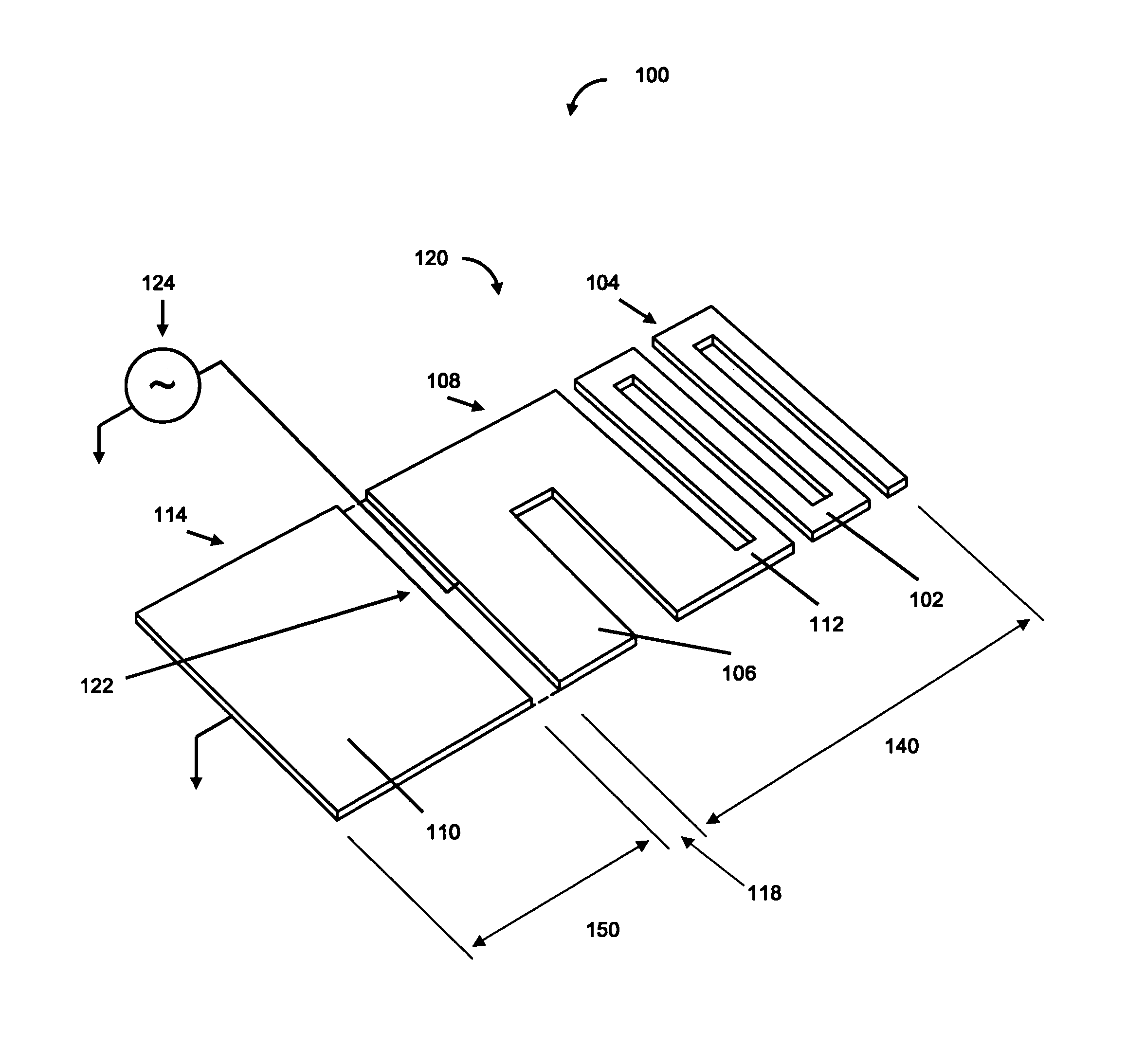
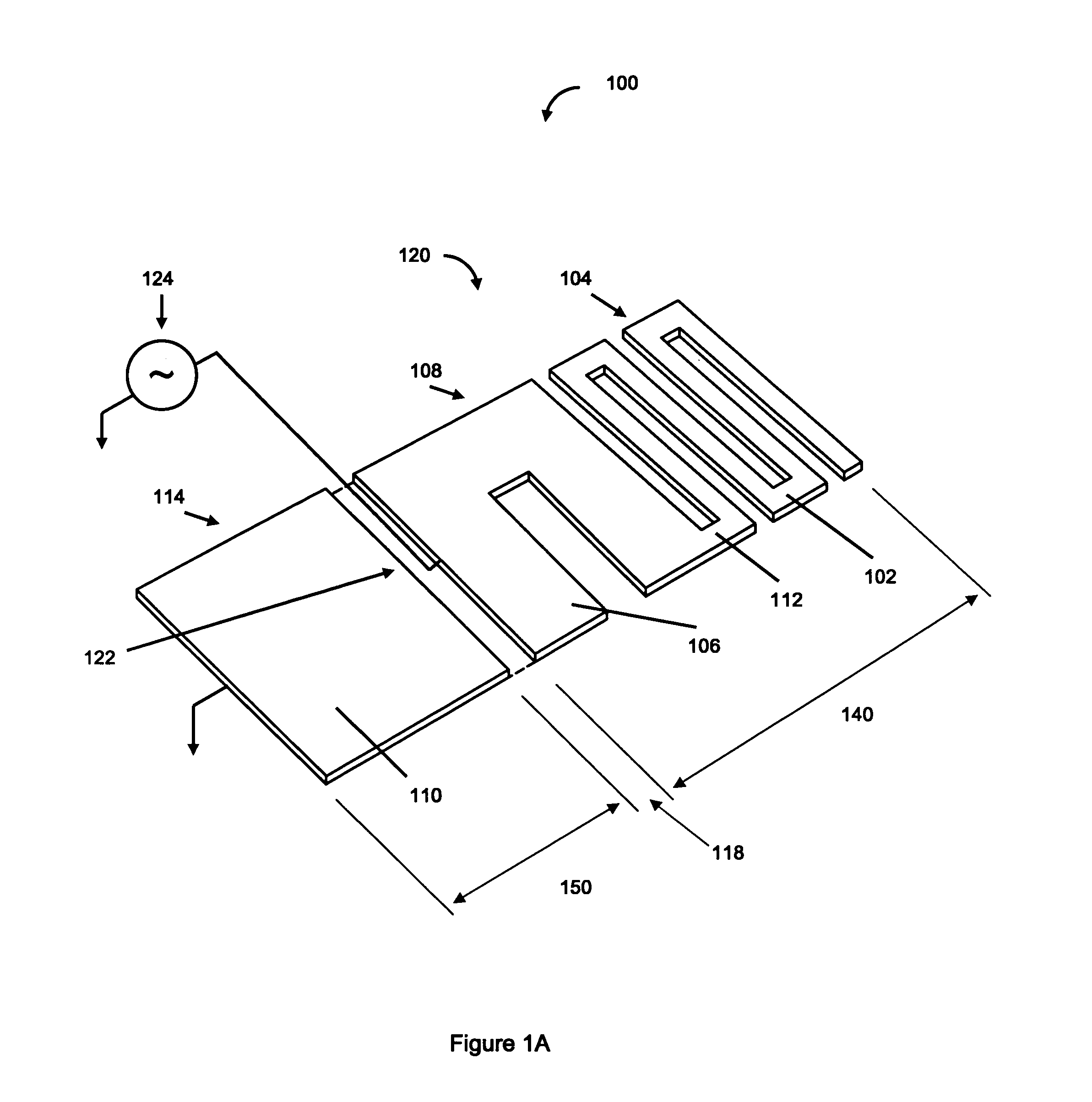
[0019]In the design of antennas to be incorporated into hand-held, portable or small devices to be affixed to objects such as in radio frequency identification (RFID) the small form factor of the devices can require the antenna to fit within a space that can be much less than a quarter of the operating wavelength of the device. For example, for devices operating in the wavelength range of λ=3 m to 0.15 cm (equivalent to an operational frequency range of 100 MHz to 200 GHz) the length of a ¼λ (monopole) antenna would lie between 75 cm and 0.04 cm, and the length of a ½λ (dipole) antenna would lie between 150 cm and 0.08 cm. As can readily be seen, ¼λ and ½λ antenna lengths are often much larger than the physical size of the device into which the antenna must fit. In an exemplary application such as an RFID device, functional limits on the size of an individual device can require an antenna to be very small, often less than 0.1λ in overall length.

[0020]The present invention provides a...


PUM


Abstract

An antenna comprises electrical conductors arranged to form a radiating element including a folded line configuration and a distributed strip configuration, where the radiating element can be in proximity to a ground conductor and / or arranged as a dipole. Embodiments of the antenna include conductor patterns formed on a printed wiring board, having a ground plane, spacedly adjacent to and coplanar with the radiating element. An antenna can comprise a distributed strip patterned on a printed wiring board, integrated with electronic components mounted on top of or below the distributed strip, and substantially within the extents of the distributed strip. Mounting of electronic components on top of or below the distributed strip has little effect on the performance of the antenna, and allows for realizing the combination of the antenna and integrated components in a compact form. An embodiment of the invention comprises an antenna including a distributed strip, integrated with a battery mounted on the distributed strip.

Description

RELATED APPLICATIONS[0001]This application is a continuation in part of U.S. application Ser. No. 11 / 243,860 filed on Oct. 5, 2005 now U.S. Pat. No. 7,345,647, Titled: “Antenna Structure with Distributed Strip”.STATEMENT REGARDING FEDERALLY SPONSORED RESEARCH OR DEVELOPMENT[0002]The United States Government has certain rights in this invention pursuant to Department of Energy Contract No. DE-AC04-94AL85000 with Sandia Corporation.FIELD OF THE INVENTION[0003]The present invention relates to the design and construction of antennas that can be used to receive and / or transmit radio frequency signals. The present invention additionally relates to compact antennas having a distributed strip structure. The present invention further relates to compact antennas having a distributed strip and integrated electronic components, such as a battery.BACKGROUND OF THE INVENTION[0004]Wireless communication systems operating at radio frequencies and having antennas, are demanding ever smaller form fac...

Claims


Application Information

Patent Timeline
Patent Type & Authority Patents(United States)
IPC IPC(8): H01Q1/38
CPCH01Q1/2208H01Q1/36H01Q1/2283H05K1/16
Inventor RODENBECK, CHRISTOPHER T.PAYNE, JASON A.OTTESEN, CORY W.
Owner NAT TECH & ENG SOLUTIONS OF SANDIA LLC
Why Eureka
Try Eureka