
Portable terminal unit

a portable terminal and terminal technology, applied in the field of portable terminal units, can solve the problems of the inability to browse information in a folded-up state, and the inability to improve the operability of the overlapping type portable terminal unit, so as to achieve the effect of improving the operability of the portable terminal uni

Inactive Publication Date: 2008-08-05
KYOCERA CORP
View PDF16 Cites 102 Cited by
  • Summary
  • Abstract
  • Description
  • Claims
  • Application Information

AI Technical Summary

Benefits of technology

The invention is a portable terminal unit that improves operability by adding various functions to the opening and closing operations. The unit has a first and second housing that can be rotated relative to each other, and an operation section on the surface of the second housing. The display section is on the first housing, and the control section controls the display. The unit can store data of multiple applications and display different screens based on the rotation of the housing. This makes the unit easier to use and improves the user experience.

Problems solved by technology

However, the folding type mobile telephone 2 as shown in FIG. 17 has a problem that while the housing 4 and the housing 6 are folded to be close to each other, the image displayed on the display screen 12 cannot be seen unless the housings 4 and 6 are opened so as to come apart from each other, and the information cannot be browsed in a folded-up state even though information is displayed on the display screen 12.
However, these operations are simple, and complex operations are not required.
Therefore, there is a problem that operability of the overlapping type portable terminal unit cannot be improved in this point.
Therefore, there is a problem that operability of the overlapping type portable terminal unit cannot be improved also in this point.

Method used


Image

  • Portable terminal unit
  • Portable terminal unit
  • Portable terminal unit

Examples


Embodiment Construction

[0039]An Embodiment of a portable terminal unit according to the invention will be specifically described with reference to drawings.

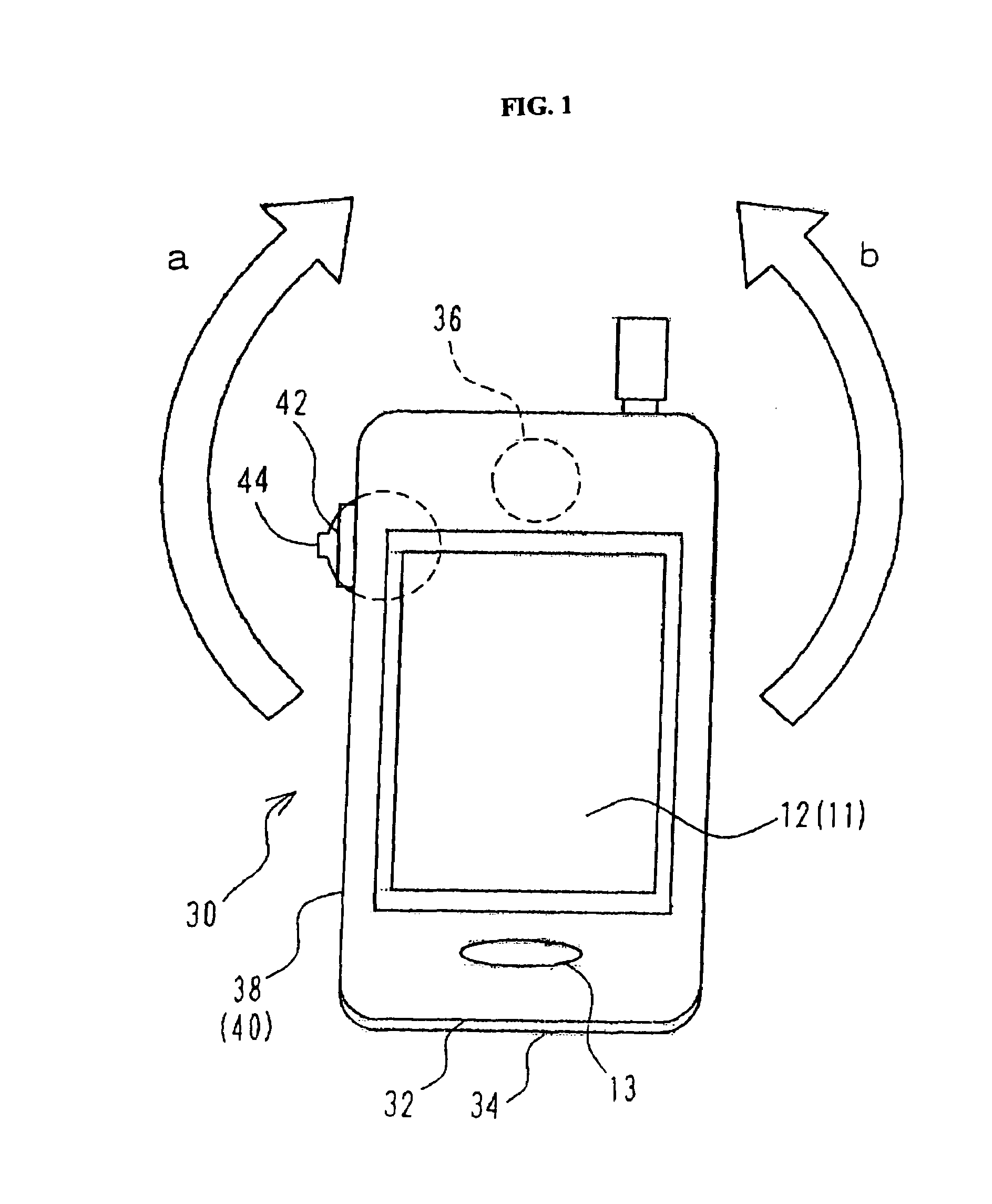
[0040]FIGS. 1 to 16 are drawings to be referred for explaining an overlapping type mobile telephone 30 (corresponding to the portable terminal unit) according to an embodiment of the invention. A mobile telephone 30 as shown in these figures will be described with the same reference numerals for the substantially same sections in the conventional folding type portable telephone 2, and duplicate description of the substantially same structure will be omitted.

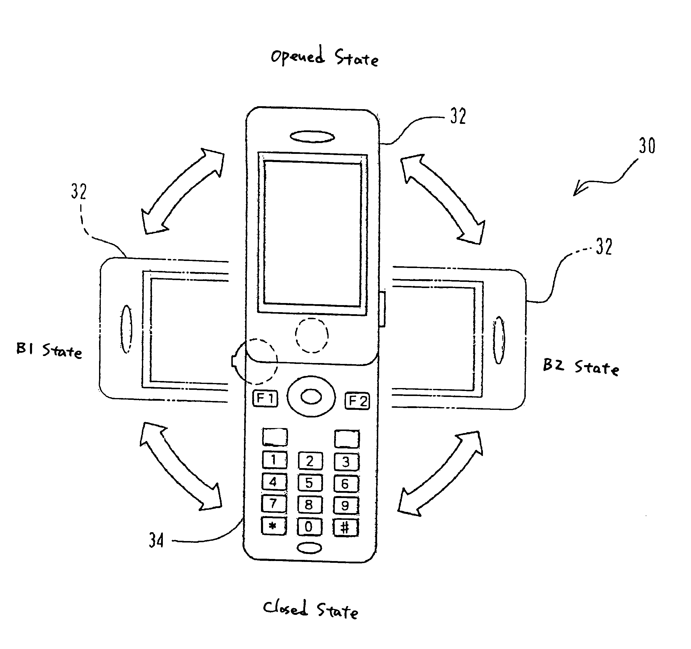
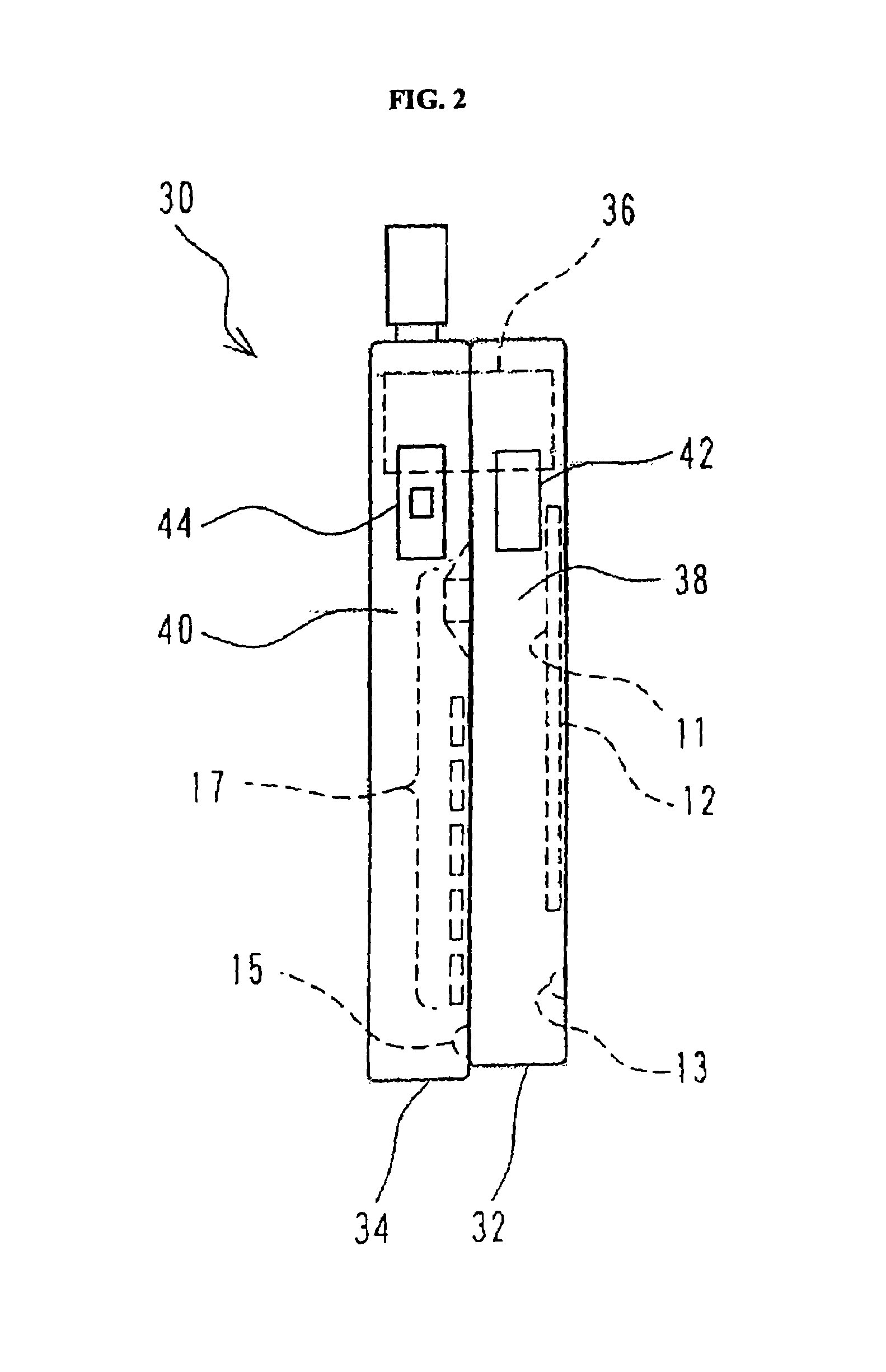
[0041]As shown in FIGS. 1 and 2, this overlapping type mobile telephone 30 includes a first housing 32 and a second housing 34 which are coupled at their end portions by a coupling section 36 having a shaft passing through the housings 32 and 34.

[0042]In the overlapping type mobile telephone 30, a display section 11 is provided on a surface of the first housing 32, which is on opposite side to the s...


PUM


Abstract

To provide a superposition type portable terminal unit in which functions other than opening and closing functions are added to opening and closing operations thereby to improve the operating performance of the portable terminal unit. In a superposition type portable terminal unit in which a first housing having at least a display section and a second housing having at least an operation section, in a close state where the display section and the operation section face in the same direction and the housings are superimposed on each other so that the operation section of the second housing is covered with the first housing, are coupled at their ends by a coupling part having an axis in a direction where the both housings are pierced, the unit is put in an open state in case that the first housing is turned about the axis from the close state in any of a clockwise direction and a counterclockwise direction; and a control unit is provided, which selects a screen so that a first screen is displayed in the display section in case that the first housing is turned in relation to the second housing clockwise from the close state, and so that a second screen is displayed in the display section in case that the first housing is turned in relation to the second housing counterclockwise.

Description

CROSS-REFERENCE TO RELATED APPLICATION[0001]This application claims priority from and incorporates herein by reference the commonly-assigned Japanese Patent Application No. 2003-012405, filed on Jan. 21, 2003.BACKGROUND OF THE INVENTION[0002]1. Field of the Invention[0003]The present invention relates to a portable terminal unit such as a mobile telephone or a PDA (Personal Digital Assistant), and specifically to a portable terminal unit configured to have a plurality of housings which are coupled to enable them to be overlapping each other.[0004]2. Description of the Related Art[0005]Conventionally, a folding type mobile telephone 2 shown in FIG. 17 is generally known as a folding type portable telephone including two housings which can be folded. In the folding type mobile telephone 2, a display screen 12 such as LCD (Liquid Crystal Display) which displays output information and a speaker 13 which are provided on an inner face 10 of one housing 4, and an operation section 16 and a...

Claims


Application Information

Patent Timeline
Patent Type & Authority Patents(United States)
IPC IPC(8): H04M1/00H04M9/00H04M1/23G06F3/048H04B1/08H04B1/38H04M1/02H04Q7/32
CPCH04M1/0243H04M1/0233H04B1/38
Inventor FUJISAWA, EIZO
Owner KYOCERA CORP
Learn More