Accumulator-type liquid sprayer

a liquid sprayer and accumulator technology, applied in the direction of liquid transfer devices, instruments, single-unit apparatuses, etc., can solve the problems of environmental contamination, troublesome container disposition, and relatively expensive sprayer types in terms of production costs

Active Publication Date: 2008-08-12
YOSHINO KOGYOSHO CO LTD
View PDF16 Cites 12 Cited by
  • Summary
  • Abstract
  • Description
  • Claims
  • Application Information

AI Technical Summary

Benefits of technology

[0010]It is an object of the present invention to eliminate the above-mentioned problems and provide a novel accumulator-type liquid sprayer capable of spraying the liquid without leakage of the liquid within the cylinder.
[0013]On this occasion, the piston end portion is brought into contact with the stopper at the annular recess formed along the outer peripheral edge of the end portion, without causing contact between the end portion and the root portion of the stopper. Therefore, even when the root portion of the stopper has a shape that otherwise tends to cause damages or deformation of the piston end portion, a positive sealing function can be achieved since the piston end portion is brought into contact with the stopper without contacting its root portion, and it is thus possible to spray the content without leakage of the liquid within the cylinder.
[0015]In this instance, major mechanisms of the accumulator-type liquid sprayer are integrated as a module, and can thus be secured to containers with various configurations. In other words, in addition to the above-mentioned technical effects obtainer by the accumulator-type liquid sprayer, it is possible to achieve a further technical effect that various changes to the product specification can be immediately accommodated.
[0017]With the above-mentioned constitution, it is possible to spray the content by a smooth operation with a reduced operating force, without causing leakage of the liquid in the cylinder. The number of components can be reduced, resulting in simplification of the assembly steps and cost reduction. All the components may be formed of a plastic material so as to eliminate requirement for fractional recovery for each material upon disposal of the sprayer.
[0021]On this occasion, the piston end portion is brought into contact with the stopper at the annular recess formed along the outer peripheral edge of the end portion, without causing contact between the end portion and the root portion of the stopper. Therefore, even when the root portion of the stopper has a shape that otherwise tends to cause damages or deformation of the piston end portion, a positive sealing function can be achieved since the piston end portion is brought into contact with the stopper without contacting its root portion, and it is thus possible to spray the content without leakage of the liquid within the cylinder.
[0024]With the above-mentioned constitution, major mechanisms of the accumulator-type liquid sprayer are integrated as a module, and can thus be secured to containers with various configurations. In other words, in addition to the above-mentioned technical effects obtainer by the accumulator-type liquid sprayer, it is possible to achieve a further technical effect that various changes to the product specification can be immediately accommodated.

Problems solved by technology

This type of sprayer is relatively expensive in terms of production cost, and requires discharge of the pressurizing medium by piercing a hole in the container when it is discarded, since in many instance the pressurizing medium remains in the container even after the dispersed fluid has been fully consumed.
Thus, the disposition of the container is troublesome, besides that discharge of the pressurizing medium into atmosphere may lead to environmental contamination.
In this instance, however, since the contact pressure between the piston and the piston guide is reduced, liquid leakage may occur in the cylinder, making it difficult to achieve an efficient spraying of the content.
In the case of accumulator-type liquid sprayer, furthermore, since the piston has a substantially flat end surface, if this flat end surface is brought into contact with a stepped surface provided in the cylinder so as to restrict displacement of the piston within the cylinder, the root portion of the stepped surface may cause deformation or damage of the piston end surface, giving rise to degradation of the tightness in the cylinder or admittance of air, making it difficult to achieve sufficient sealing function.

Method used


Image

  • Accumulator-type liquid sprayer
  • Accumulator-type liquid sprayer
  • Accumulator-type liquid sprayer

Examples


first embodiment

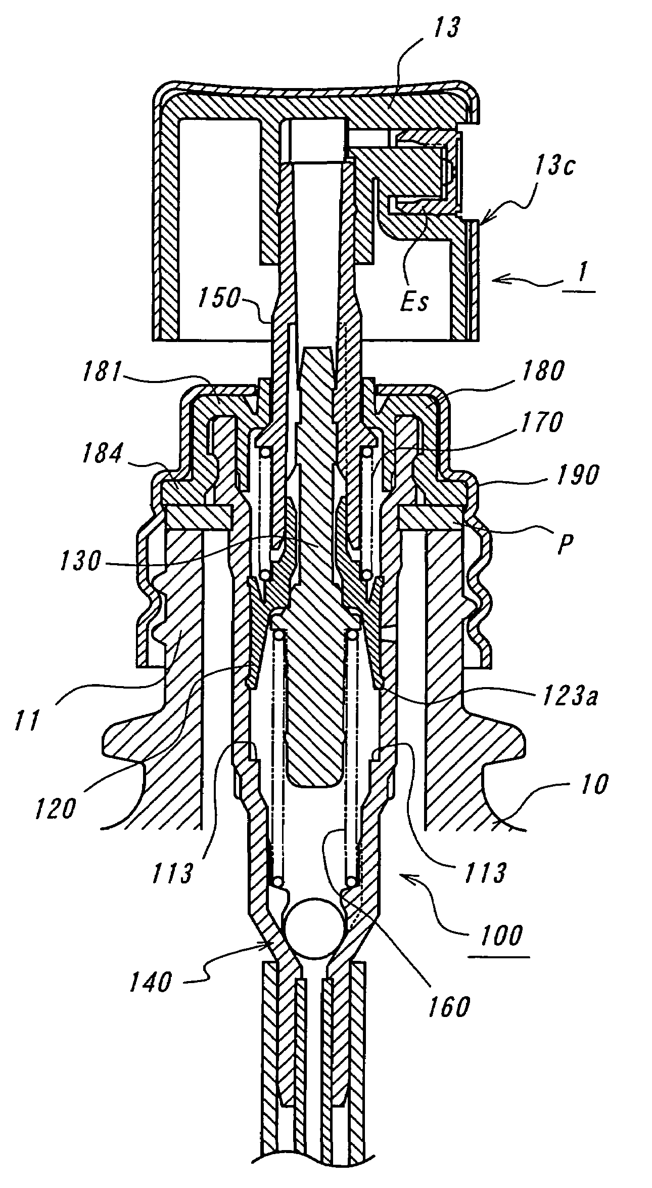
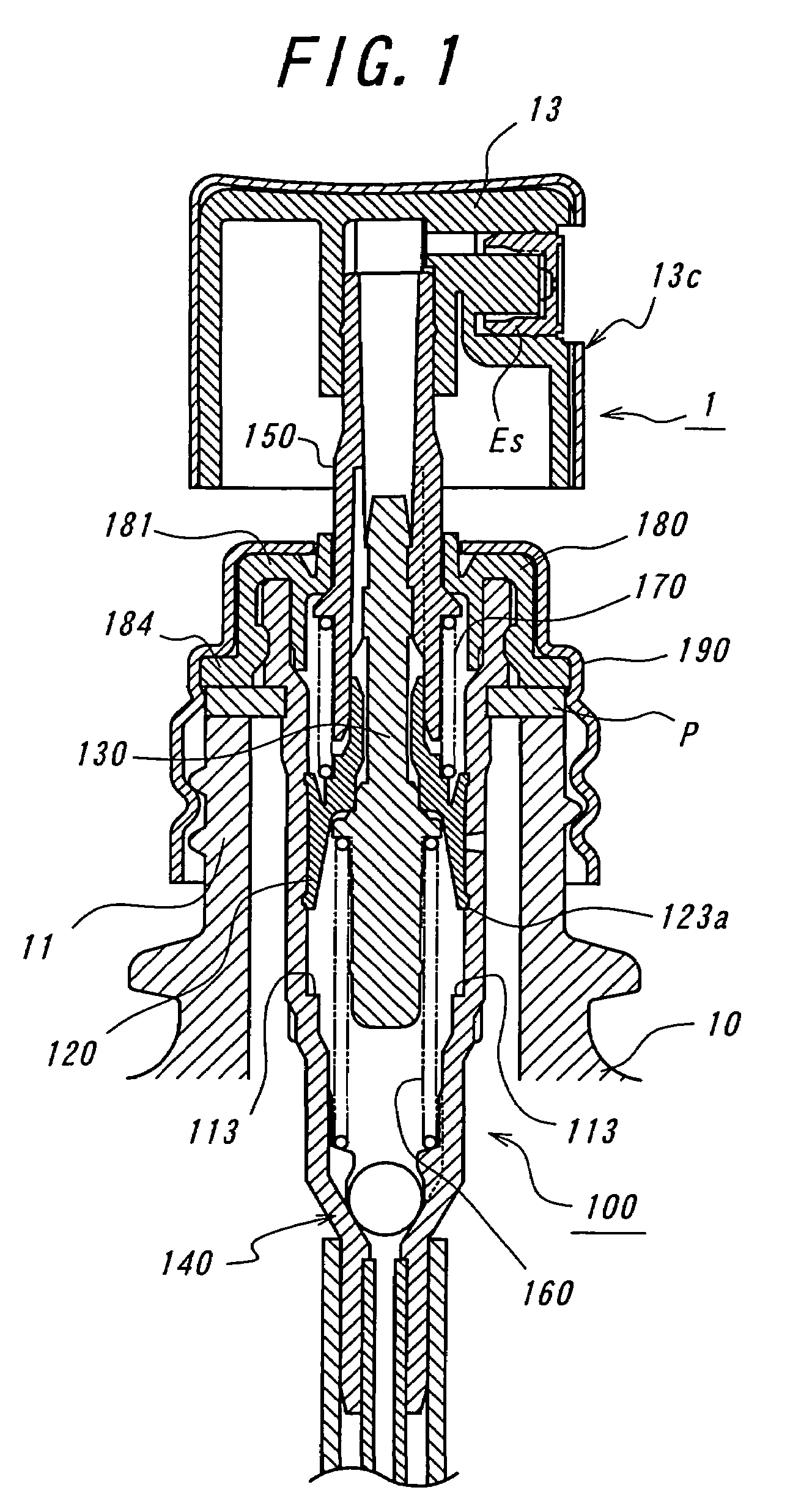
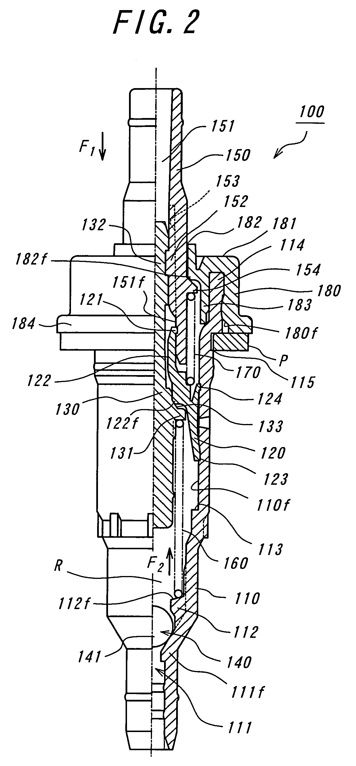
[0044]FIG. 1 is a sectional view of an accumulator-type liquid sprayer according to the present invention, and FIG. 2 is a partly sectional side view of a module used in the accumulator-type liquid sprayer 1 shown in FIG. 1.

[0045]In FIG. 1, reference numeral 10 denotes a container to be filled with a content, reference numeral 11 denotes a mouth portion of the container 10, and reference numeral 100 denotes a module that is shown in FIG. 2.

[0046]As shown in FIG. 2, the module is comprised of nine parts, i.e., a cylinder 110. a piston 120, a piston guide 130, a check valve 140, a hollow stem 150, a first resilient member in the form of a spring 160, a second resilient member in the form of a spring 170, a cover member 180 and a seal element P.

[0047]The cylinder 110 has a seat portion 111f arranged adjacent to a suction port 111 for receiving a ball 141 thereon, and a plurality of ribs 112 for restricting the displacement of the ball 141. The spring 160 is arranged on the upper surfac...

second embodiment

[0066]FIG. 6 is a sectional view of the accumulator-type liquid sprayer according to the present invention, which also uses the module 100. Elements shown in FIGS. 1 to 5 are denoted by the same reference numerals and explanation thereof is omitted.

[0067]The accumulator-type liquid sprayer 2 shown in FIG. 6 is of spray-type similar to that shown in FIG. 1, which is secured to the mouth portion 11 of the container 10 through a base member 191, though the head cover 13c is detachably secured to the base member 191.

[0068]In the case of the accumulator-type liquid sprayer 2 also, the cover member 180 has an outer peripheral portion integrally provided with a flange portion 184. Therefore, it can be secured to the moth portion 11 of the container 10 simply by undercut fitting the base member 191 with the flange portion 184 of the cover member 180, and it is thus possible to achieve a cost reduction since adhesive or connector elements for the connection with the cover member 180 is not r...

third embodiment

[0070]FIG. 7 is a sectional view of the accumulator-type liquid sprayer according to the present invention. Elements shown in FIGS. 1 to 6 are denoted by the same reference numerals and explanation thereof is omitted.

[0071]The accumulator-type liquid sprayer 3 shown in FIG. 7 is of the type wherein the cylinder 110 is secured to the mouth portion 11 of the container 10 through a base member 192. In this instance also, since the front end portion 123 of the piston 120 is formed with an annular recess 123a along the outer peripheral edge of the end portion, even when the root portion 113a of the stepped surface 113 has a shape that otherwise tends to cause damages or deformation of the front end portion 123 of the piston 120, a positive sealing function can be achieved since the front end portion 123 of the piston 120 is brought into contact with the stepped surface 113 without contacting its root portion 113a, and it is thus possible to spray the content without leakage of the liquid...


PUM


Abstract

An accumulator-type liquid sprayer includes a piston arranged in a cylinder, a piston guide extending through a passage extending therethrough in an axial direction of the piston, so as to be engageable with, and disengageable from the piston, cooperating with the piston and the cylinder to form a space region for sucking and pressurizing a liquid, a check valve for opening a suction port of the cylinder during suction of the liquid, and a hollow stem slidably fitted with an outer side of the piston in a liquid-tight manner and engaging with an end portion of the piston guide. A first resilient member urges the piston guide against the piston for maintaining a closed state of the passage in the piston, and a second resilient member urges the piston against the piston guide for adjusting a spraying pressure of the liquid. A stopper is arranged in the cylinder, for positioning the piston before the content is sprayed to provide increased contact surface pressure so as to maintain the closed state of the passage. The piston has an end portion which can be brought into contact with the stopper, and which is formed with an annular recess extending along an outer peripheral edge of the end portion.

Description

BACKGROUND ART[0001]1. Technical Field[0002]The present invention relates to an accumulator-type liquid sprayer, and aims to effectively prevent leakage of the liquid within a cylinder of the sprayer.[0003]2. Prior Art[0004]As a sprayer for spraying finely atomized liquid such as lotion, cologne or perfume, aerosol-type sprayers are widely used wherein dispersed fluid is filled in a container together with pressurizing medium. This type of sprayer is relatively expensive in terms of production cost, and requires discharge of the pressurizing medium by piercing a hole in the container when it is discarded, since in many instance the pressurizing medium remains in the container even after the dispersed fluid has been fully consumed. Thus, the disposition of the container is troublesome, besides that discharge of the pressurizing medium into atmosphere may lead to environmental contamination.[0005]Therefore, it is a recent trend to reevaluate accumulator-type liquid sprayer which does ...

Claims


Application Information

Patent Timeline
Patent Type & Authority Patents(United States)
IPC IPC(8): B67D5/40B05B11/00B65D47/34B67D7/58
CPCB05B11/3077B05B11/3025B05B11/1025B05B11/1077B05B9/04B05B11/00
Inventor KUWAHARA, KATSUHITOGOTO, TAKAYUKI
Owner YOSHINO KOGYOSHO CO LTD
Why Eureka
Try Eureka