Electroluminescence light emitting display system

Inactive Publication Date: 2006-09-19
TOMY CO LTD
View PDF53 Cites 14 Cited by
  • Summary
  • Abstract
  • Description
  • Claims
  • Application Information

AI Technical Summary

Benefits of technology

[0037]According to the system having such construction, such coloring enables not only making the electrode pattern invisible from the front side but also widening the range of choice for design from

Problems solved by technology

However, the EL light emitting sheet disclosed in Patent Document 1 cannot form the display electrode easily, since the method needs to form the electrically conductive material on the light-emitting layer as a

Method used


Image

  • Electroluminescence light emitting display system
  • Electroluminescence light emitting display system
  • Electroluminescence light emitting display system

Examples


Embodiment Construction

[0049]Hereinafter, the preferred embodiments of the present invention will be described in detail by reference to the attached drawings.

A. EL Light Emitting Sheet

1. Whole Configuration

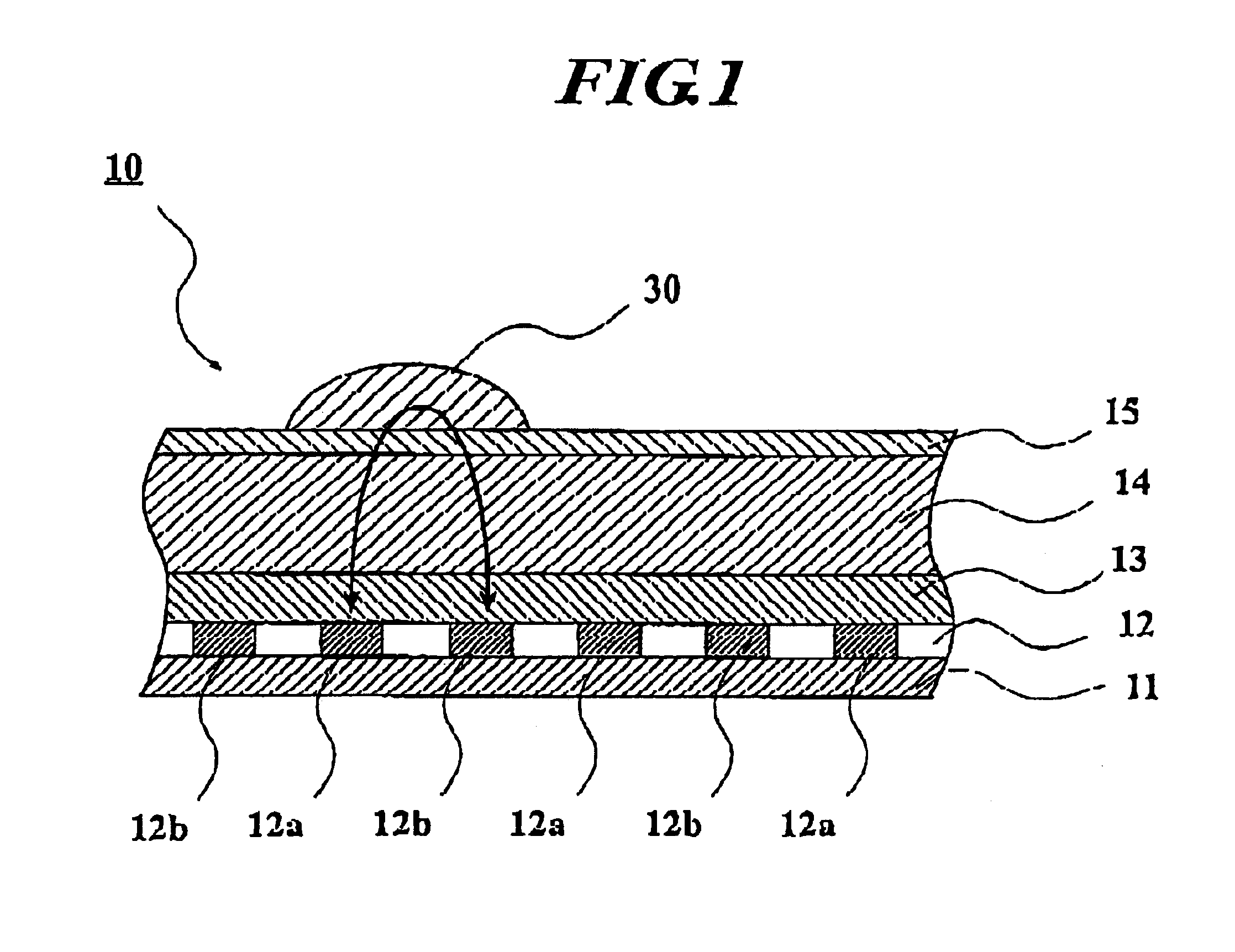
[0050]FIG. 1 is an enlarged sectional view of a principal part of an EL light emitting sheet 10 to which the present invention is applied. In FIG. 1, the EL light-emitting sheet 10 is formed by laminating a base layer 11, an electrode layer (electrode section) 12, a waterproof layer 13, an EL light-emitting layer 14 and a top coat layer 15 in order.

2. Detailed Configuration

(1) Base Layer 11

[0051]The base layer 11 is made of an insulating material such as polyethylene terephthalate (PET) or the like. The base layer 11 may be configured as a base film (substrate sheet). In this case, the base film is made of a transparent or opaque resin. As the resin in this case, for example, PET is used. Incidentally, the base layer 11 may be made of glass.

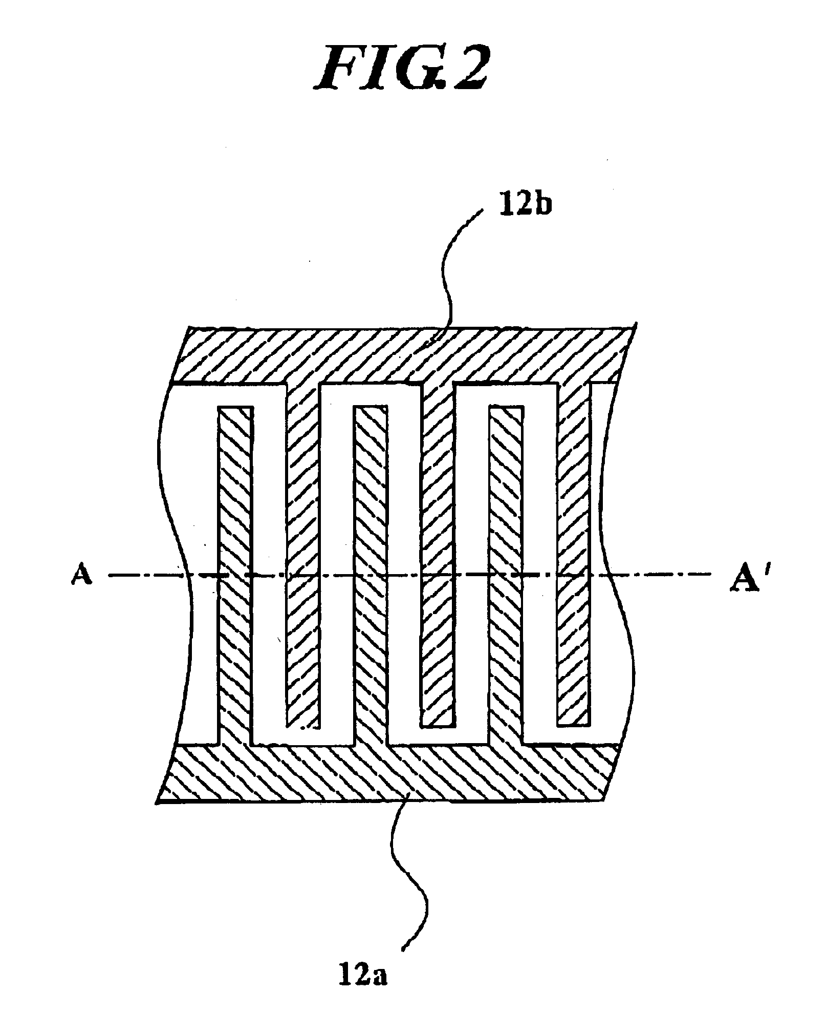
(2) Electrode Layer 12

[0052]The electrode layer 12 having a pr...


PUM


Abstract

An electroluminescent light emitting system, having an electroluminescent light-emitting layer containing electroluminescent light-emitting elements, one surface side of which receives an AC electric field forming material thereon; an electrode section including a first electrode layer with a predetermined first pattern and a second electrode layer with a predetermined second pattern, which are disposed relatively close to but electrically spaced from each other on another surface side of the electroluminescent light emitting layer; and a waterproof resin layer provided between at least one of the first electrode layer and the second electrode layer electrode section, and the electroluminescent light-emitting layer. The AC electric field forming material on the one surface side enables an AC electric field to be generated in the electroluminescent light-emitting layer with an AC voltage applied between the first electrode layer and the second electrode layer.

Description

BACKGROUND OF THE INVENTION[0001]1. Field of the Invention[0002]The present invention relates to an electroluminescence light emitting system including an EL light emitting layer.[0003]2. Description of the Related Art[0004]An electroluminescence, hereinafter, which may be referred to EL simply, material is known as one of light emitting materials. Various types of EL light emitting sheets have been developed and put to practical use. The EL light emitting sheet is generally formed by laminating a first electrode, a light-emitting layer, an insulating layer, i.e., a light reflecting layer, a second electrode and a protective layer in order. Generally, by applying an alternating voltage (AC voltage) between the first electrode and the second electrode, a fluorescent material, i.e., EL light emitting elements, in the light-emitting layer emits light.[0005]As another type of EL light emitting sheet, one having peculiar operation and effects is known (see, for example, Patent Document 1...

Claims


Application Information

Patent Timeline
IPC IPC(8): G09F9/00H05B33/00G06F1/16G09F13/04G09F13/22G09G3/20G09G3/30H01L27/32H05B33/20H05B33/22H05B33/26H05B44/00
CPCH01L27/3237H01L51/5203H05B33/08H05B33/22H05B33/26H05B33/20Y02B20/325H05B45/00H10K59/10H10K50/805H05B33/00Y02B20/30
Inventor WATANABE, KIMITAKAYAMANAKA, HIROYUKI
Owner TOMY CO LTD
Why Eureka
Try Eureka