
Mounting device for the headrest of a vehicle seat

a technology for vehicle seats and mounting devices, which is applied in the direction of seat furniture, vehicle safety belts, applications, etc., can solve the problems of high manufacturing cost, high manufacturing and assembly costs, and often difficult or impossible requirements, and achieves low friction and simple and cost-effective construction.

Active Publication Date: 2008-08-12
FAURECIA AUTOSITZE
View PDF49 Cites 35 Cited by
  • Summary
  • Abstract
  • Description
  • Claims
  • Application Information

AI Technical Summary

Benefits of technology

The invention is a mounting device for a vehicle seat headrest that compensates for tolerances and dimensional variations to reduce friction during headrest adjustment. The device includes two guide sleeves for headrest rods, a receptacle device for holding the guide sleeves, and a first guide sleeve that is held and rests at multiple bearing points in the backrest. The second guide sleeve is pivotably held in the receptacle device and can be moved in the transverse direction. This compensates for any deviations in parallelism or dimensional variations in the headrest rods and receptacle devices. The first guide sleeve is securely fastened without being adjustable in the axial direction or rotationally / linearly. The receptacle devices can be tubular or openings in the backrest. The second guide sleeve can be mounted in the receptacle device and assumes various pivot positions with different track widths or tolerances.

Problems solved by technology

In practice, these requirements are frequently difficult or impossible to fulfill.
For the components, strict requirements with regard to dimensional consistency and precision of positioning result, which in turn leads to high manufacturing and assembly costs.
In particular, headrest frames having a very precise degree of parallelism and a precise track width result in high manufacturing costs.
However, a mounting device of this type involves a complex construction with multiple components, and a correspondingly high assembly cost.

Method used


Image

  • Mounting device for the headrest of a vehicle seat
  • Mounting device for the headrest of a vehicle seat
  • Mounting device for the headrest of a vehicle seat

Examples


Embodiment Construction

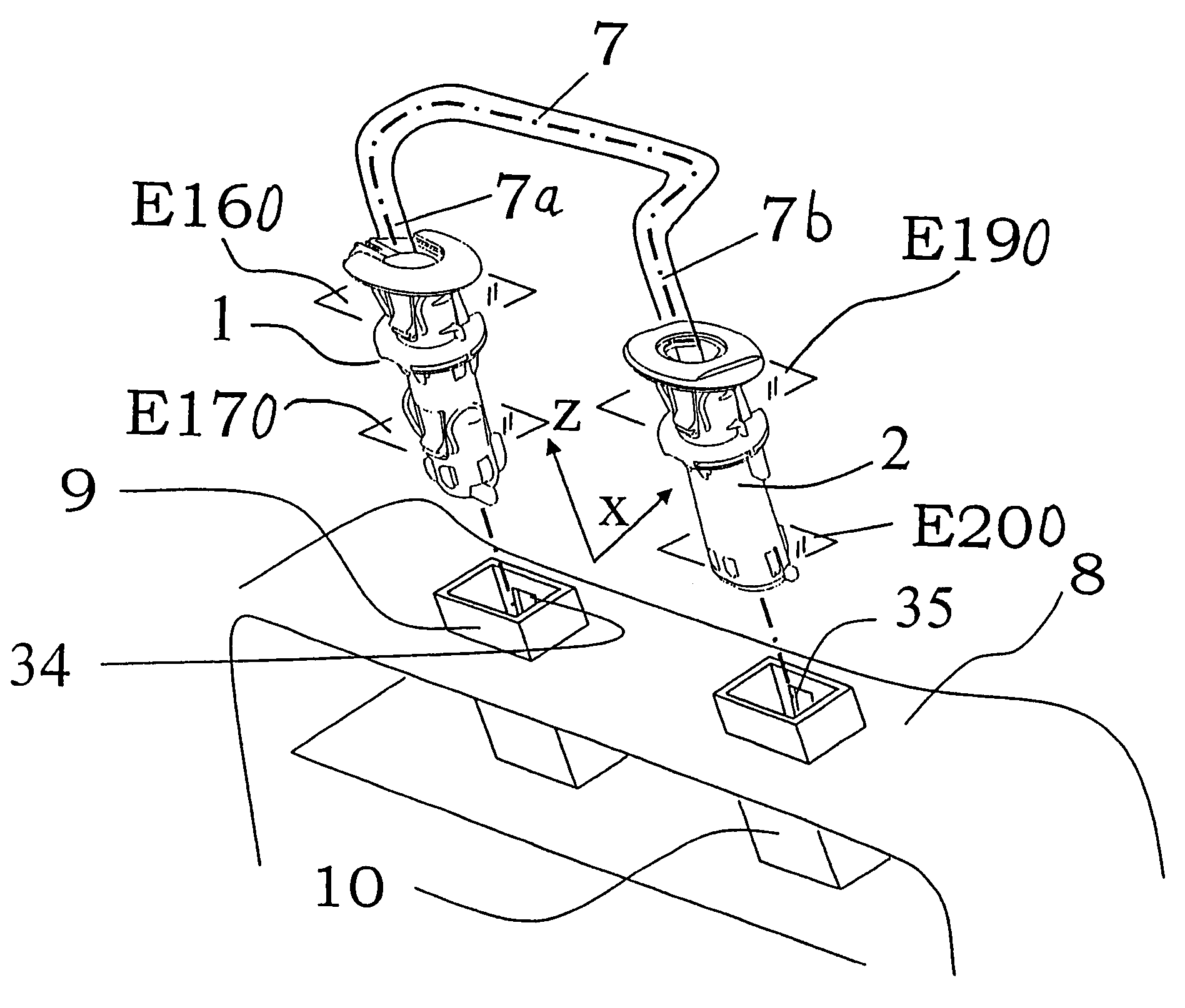
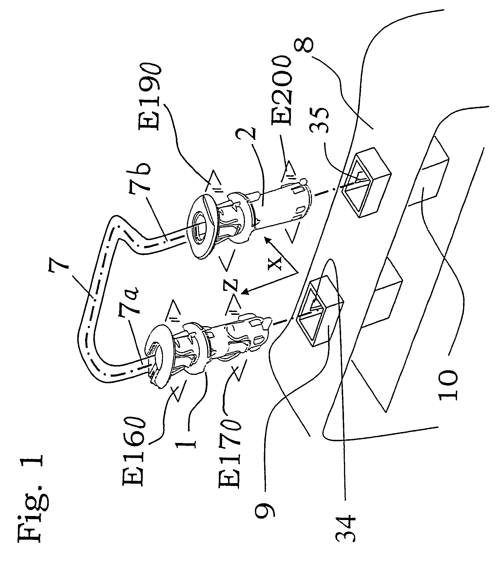
[0034]On a backrest 8, an unillustrated headrest is mounted such that its height can be adjusted, or such that it can be shifted in the vertical Z direction, by way of a headrest frame 7. For this, the headrest frame 7 is adjustably held with its left headrest rod 7a in a left guide sleeve 1 and with its right headrest rod 7b in a right guide sleeve 2, as will be described further below.

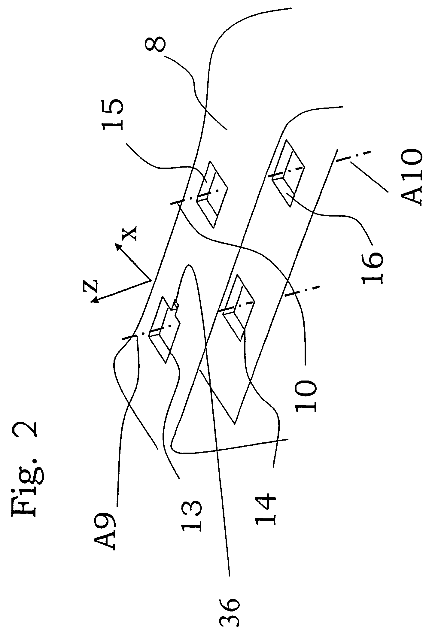
[0035]The guide sleeves 1, 2 are in turn inserted from the top into respective receptacle devices 9, 10 or 13, 14, 15, 16 that are secured in the backrest 8. According to the embodiment shown in FIG. 1, a left receptacle 9 and a right receptacle 10—in the direction of travel X—serve as receptacle devices secured in the backrest, each of which is configured to be tubular with a rectangular cross-section. According to the embodiment of FIG. 2, the receptacle devices secured in the backrest are configured as rectangular openings in a solid structural material, for example horizontal plates, comprising a...


PUM


Abstract

Mounting device for a headrest with two headrest rods for a vehicle seat, which includes a first guide sleeve for the height-adjustable accommodation of a first headrest rod, a second guide sleeve for the height-adjustable accommodation of a second headrest rod, and a first receptacle device secured in the backrest, in which the first guide sleeve is held and rests at at least two axially spaced bearing points. A second receptacle device is secured in the backrest, within which the second guide sleeve can be shifted at least in the transverse direction. The second guide sleeve rests in the second receptacle device, which is secured in the backrest. Advantageously, the second guide sleeve is pivotably held in the second receptacle device, which is secured in the backrest, and the second headrest rod is pivotably held in the second guide sleeve.

Description

CROSS-REFERENCE TO RELATED APPLICATION[0001]This application claims priority of German application no. 10 2005 019 946.1, filed Apr. 29, 2005, which is incorporated herein by reference.FIELD OF THE INVENTION[0002]The invention relates to a mounting device for the headrest of a vehicle seat. More particularly, the invention relates to a mounting device for the headrest of a vehicle seat headrest with two headrest rods, a first and second guide sleeves for height-adjustably receiving first and second headrest rods, and the first and second guide sleeves being received in the receptacle devices when secured in a vehicle backrest.BACKGROUND OF THE INVENTION[0003]To allow the support and height-adjustable mounting of headrests, welded pieces of pipe or openings are customarily mounted in the upper regions of backrests, and are in turn used to affix guide sleeves for height-adjustably receiving the headrest rods of the headrest frame.[0004]The guide sleeves must maintain the adjusted heig...

Claims


Application Information

Patent Timeline
Patent Type & Authority Patents(United States)
IPC IPC(8): A47C7/36
CPCB60N2/4808B60N2/809
Inventor KRAFT, DIETERMERKERT, LARSHIELCKERT, RICHARD
Owner FAURECIA AUTOSITZE
Learn More