Bio-passage for disrupting laminar flow

a technology of laminar flow and bio-passage, which is applied in the field of bio-passage for disrupting laminar flow, can solve the problems of affecting the ability of fish to migrate through these regions, affecting reducing the flow of fish, so as to achieve the effect of reducing the flow

Active Publication Date: 2008-08-12
TUCKER RANDALL L
View PDF8 Cites 3 Cited by
  • Summary
  • Abstract
  • Description
  • Claims
  • Application Information

AI Technical Summary

Benefits of technology

[0007]More particularly, the apparatus limits flow velocity through the passage to improve migration for fish, particularly during high flow events.
[0011]A primary benefit of the invention is the ability to reduce the flow within the passage irrespective of the flow external to the apparatus.
[0013]Still another benefit is the improved environment for fish migration during high water or high flow events.

Problems solved by technology

When encountering a narrow region during an increased flow event, the velocity or flow rate reaches a level that makes it difficult for the fish to pass through and the fish tend to cease their migration at these regions and these high flow events / regions become choke points.
Unfortunately, this only exacerbates the ability of fish to migrate through these regions.
Thus, present arrangements simply do not provide a passage or region that is effective to reduce the velocity and allow the fish to more easily migrate therethrough, irrespective of the increased flow velocity in the stream or culvert.

Method used


Image

  • Bio-passage for disrupting laminar flow
  • Bio-passage for disrupting laminar flow
  • Bio-passage for disrupting laminar flow

Examples


Embodiment Construction

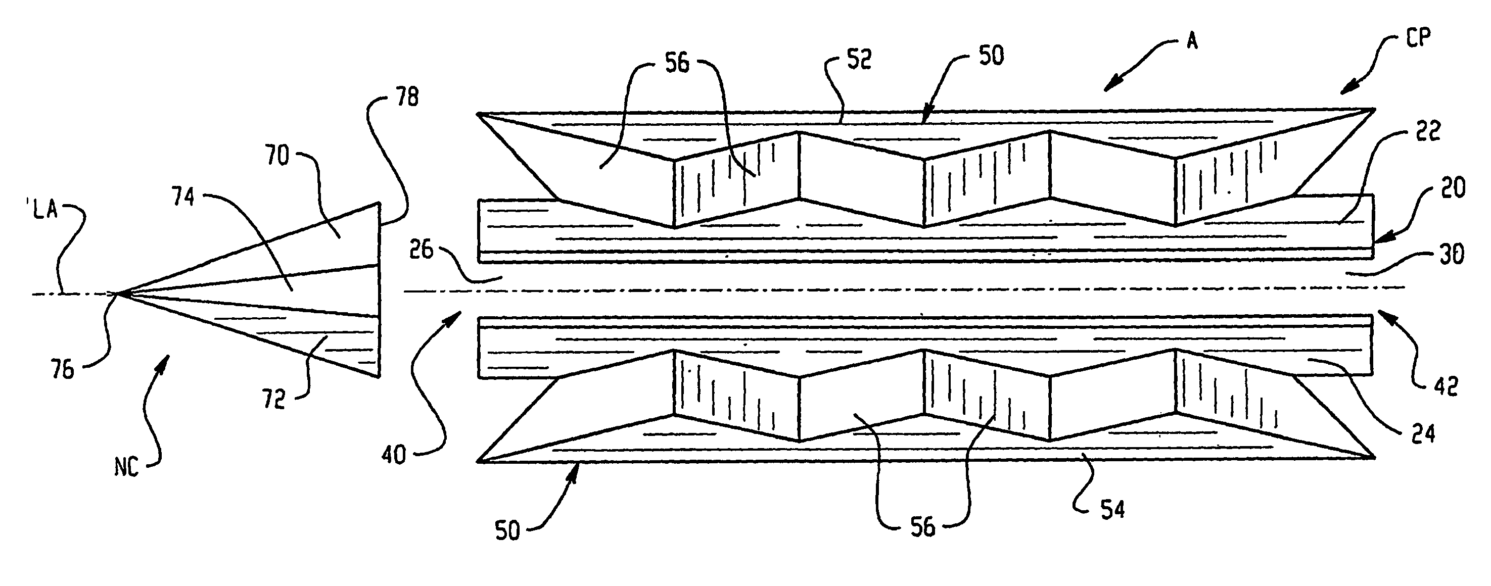
[0021]Turning first to FIGS. 1-3, an apparatus, also referred to as a bio-passage assembly A is shown in plan view. It includes a channel portion CP and a deflector or nosecone portion NC.

[0022]More specifically, the channel portion CP includes a housing 20 which includes first and second sidewalls 22, 24. As evident in FIGS. 1-3, the sidewalls 22, 24 are disposed in angled relation and define a generally trapezoidal-shaped passage 26 (FIG. 3). That is, the passage is wider at a bottom portion 28 and narrower at an upper portion 30 that terminates in an opening 32. The opening preferably extends along the longitudinal extent of the channel portion. The passage has a first or inlet end 40 that communicates along the length of the channel portion with a second or outlet end 42 (FIG. 1). For reasons which will become more apparent below, this passage has a reduced velocity flow therethrough in comparison to the flow velocity of the remainder of the waterway in which the assembly is ins...


PUM


Abstract

An apparatus or biopassage (A) includes a housing (20) dimensioned for receipt in a waterway during an increased flow event. The housing has a passage: (26) that provides a region of reduced flow generally irrespective of the flow external to the passage. A flow disrupter (50) disturbs laminar flow in the waterway above the passage. A preferred embodiment of the disrupter includes surfaces (52, 54) disposed in angled relation relative to a common apex (60) located above a longitudinal opening (30passage. The surfaces include a series of peaks and valleys formed by angled planar portions (56) in one arrangement. A deflector (NC) is positioned upstream of an inlet end (40) of the passage to direct water away from the passage.

Description

[0001]This application claims the benefit of PCT patent application Ser. No. PCT / US04 / 025634, filed on 9 Aug. 2004 which claims the benefit of U.S. Provisional Patent Application Ser. No. 60 / 493,511, filed on Aug. 8, 2003.BACKGROUND OF INVENTION[0002]This application is directed to an apparatus for reducing flow through a housing to a significantly different rate or velocity than a flow exterior to the housing. The invention finds particular application in allowing passage of migrating fish, for example, under bridges, through road culverts, etc., where a waterway is confined to a confined region; however, the application will find use in related environments and applications.[0003]It is not uncommon for a waterway or stream to be confined to a localized region where it passes beneath a bridge, through a road culvert, etc. During periods of heavy rainfall, for example, there is an attendant increase in the amount of water that flows through such regions, and the velocity in the wate...

Claims


Application Information

Patent Timeline
Patent Type & Authority Patents(United States)
IPC IPC(8): E02B3/00E02B8/08
CPCE02B8/085Y02A40/60
Inventor TUCKER, RANDALL L.
Owner TUCKER RANDALL L
Why Eureka
Try Eureka