Transfer plant and method for loading and unloading containers from container ships

a technology for container ships and transfer plants, which is applied in the direction of waterborne vessels, braking devices for hoisting equipment, cranes, etc., can solve the problems of inability to balance out the higher speed of trolley travel, inability to inability to further increase the speed of trolleys, so as to achieve significant increases in handling performance, the effect of reducing the time spent by the container ship at the dock and substantially increasing the speed of travel

Inactive Publication Date: 2008-08-12
GOTTWALD PORT TECH
View PDF13 Cites 23 Cited by
  • Summary
  • Abstract
  • Description
  • Claims
  • Application Information

AI Technical Summary

Benefits of technology

[0006]The purpose of the present invention is therefore to create a novel design of a transfer plant and a method for loading and unloading of containers, preferably ISO containers, from container ships at seaports, such that the handling performance can be significantly increased and thus the time spent by the container ship at dock can be substantially reduced. At the same time, one should make sure that the crane operator is no longer exposed to the great stresses that arise from the fast acceleration and deceleration and the high speeds of travel of the trolleys. In particular, one goal of the present invention is to automatically perform the overwhelming majority of the unloading and loading process.

Problems solved by technology

However, the hoisting and lowering events represent only one of many lost times, and a prime criterion for the handling capacity of the container bridge is first and foremost the duration of a load alternation of the crane trolleys.
With increasing size of ship and, thus, increasing width of ship, the sea-side extension arm and thus the horizontal travel distance of the trolleys becomes increasingly longer, and this cannot be balanced out by higher speeds of travel of the trolleys.
The maximum trolley travel speeds currently achieved in container bridges of around 4 m / s are on the order of magnitude just within the capabilities of the crane operators; any further increase in trolley speed is hardly feasible.

Method used


Image

  • Transfer plant and method for loading and unloading containers from container ships
  • Transfer plant and method for loading and unloading containers from container ships
  • Transfer plant and method for loading and unloading containers from container ships

Examples


Embodiment Construction

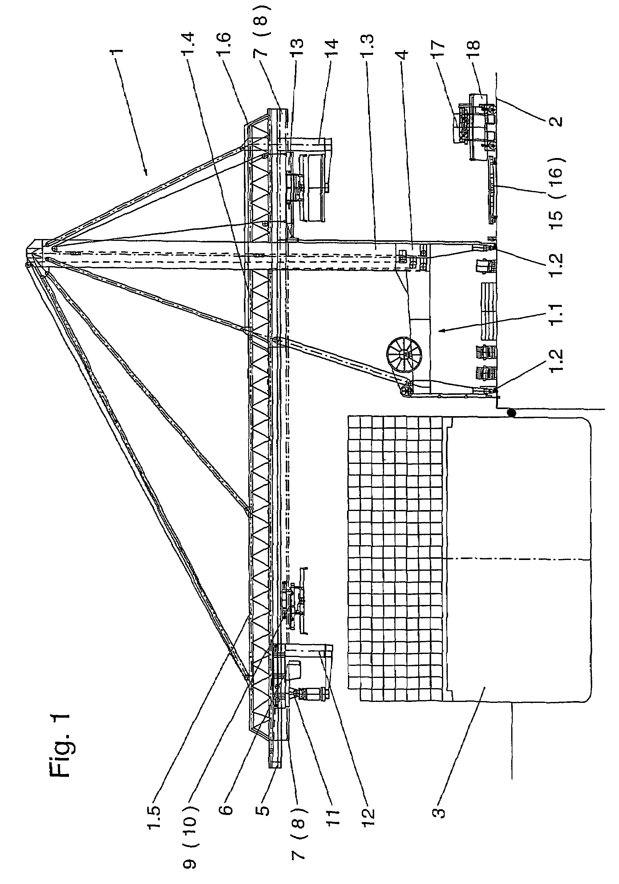
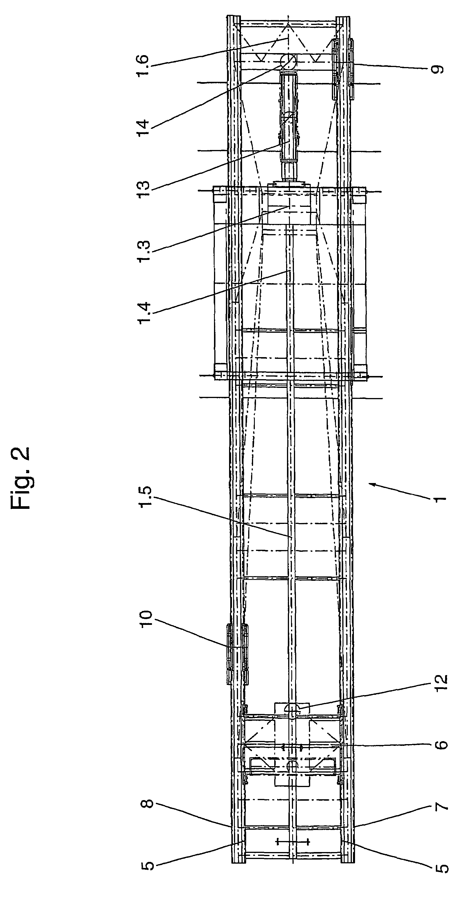
[0053]FIG. 1 shows a transfer plant 1 with a container ship 3 lying at dock 2. The transfer plant 1 consists primarily of a gantry 1.1, which rests on the dock by four multiple-wheel rail traversing mechanisms 1.2, a tower type vertical support 1.3, and a horizontal extension arm 1.4, 1.5 and 1.6, fastened to it. This extension arm consists of a rigid base arm 1.4 at the sea side, a swivel arm 1.5 mounted on it at the sea side, and a rigid extension arm 1.6 at the land side.

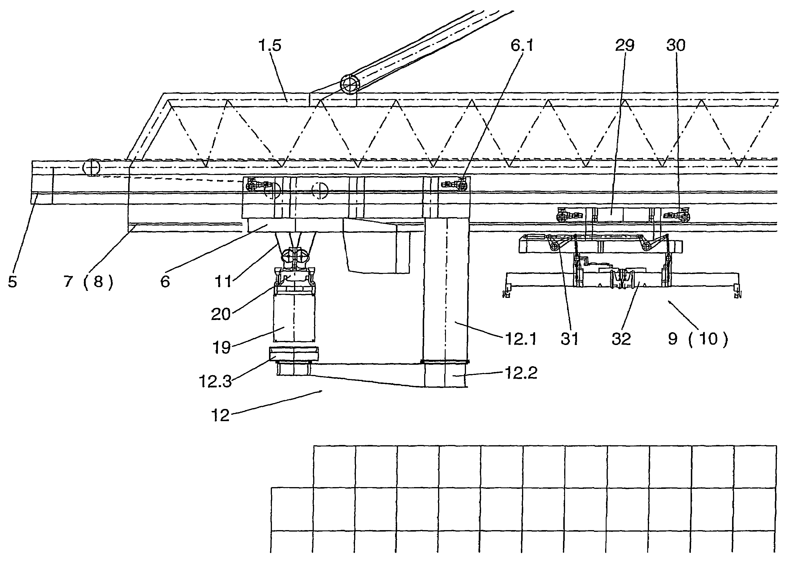
[0054]The cable winches and drive unit 4 of the transfer plant are arranged in the cross beam 1.7 of the gantry 1.1 at the land side. The two extension arms 1.4 and 1.5 at the sea side carry at an upper level of their underside a railway 5 for a trolley 6 and, to the side of that on a lower level, at least one railway 7 and 8 for a horizontal conveying device 9 and 10. The railway 5 of the trolley 6 ends at the vertical support 1.3, but the railways 7 and 8 are continued past the side of the vertical support 1.3 ...


PUM


Abstract

The invention relates to a transfer plant, especially for loading and unloading ISO containers from container ships at seaports, comprising a vertical support which is propped up on the land side and on which a horizontal extension arm is braced. Said horizontal extension arm, along which a horizontal conveying device can be displaced, protrudes across the ship that is to be unloaded on the sea side. The horizontal conveying device cooperates with hoisting and lowering devices which pick up and put down the containers. The aim of the invention is to create a redesigned transfer plant and a method for loading and unloading containers, preferably ISO containers, from container ships in seaports, which allow the transfer rate to be significantly increased and consequently the lay times of the container ships at the pier to be substantially reduced. Said aim is achieved by disposing at least two horizontal conveying devices (9, 10) on the horizontal extension arm (1.4, 1.5, 1.6), which can be displaced independently of each other along said horizontal extension arm (1.4, 1.5, 1.6) between the hoisting and lowering devices (11, 13) that are located on the land side and the sea side. In addition, intermediate storage devices (12, 14), into which the containers can be placed and from which said containers can be picked up by the hoisting and lowering devices (11, 13) that are located on the land side and the sea side and the horizontal conveying devices (9, 10), are disposed on the horizontal extension arm in the area of the hoisting and lowering devices (11, 13) that are located on the land side and the sea side.

Description

BACKGROUND OF THE INVENTION[0001]The invention relates to a transfer plant, especially for loading and unloading containers from container ships at seaports, with a vertical support which is propped up at the land side and on which a horizontal extension arm is braced, which protrudes across the ship that is to be unloaded on the sea side and along which a horizontal conveying device can travel, which cooperates with hoisting and lowering devices that pick up and put down the containers, being arranged at the land and sea side and also on the horizontal extension arm.[0002]The invention also relates to a method for loading and unloading containers from container ships at seaports, making use of the aforesaid transfer plant.[0003]A container transfer plant with the above described features is known, for example, from DE 40 40 072 A1. The known solution attempts to reduce as much as possible the lost time during the loading and unloading of container ships, which arises at full extens...

Claims


Application Information

Patent Timeline
Patent Type & Authority Patents(United States)
IPC IPC(8): B63B27/00B65G67/60B66C11/12B65G63/00B66C19/00
CPCB66C19/002B65G63/004B66C19/00B66C13/00
Inventor FRANZEN, HERMANNKROLL, JOACHIM
Owner GOTTWALD PORT TECH
Why Eureka
Try Eureka