Method for testing battery condition

a battery condition and test method technology, applied in the field of methods, can solve the problems of low battery discharge energy, battery cannot be tested at high current conditions, inaccurate results received for predicting cca, soc and soh

Inactive Publication Date: 2008-08-12
BATTERY CONTROL CORP
View PDF4 Cites 5 Cited by
  • Summary
  • Abstract
  • Description
  • Claims
  • Application Information

AI Technical Summary

Benefits of technology

[0014]It is a purpose of the present invention to provide an electronic battery testing method and apparatus for determining the accurate condition of a battery without damaging the battery, based on a battery high current shortening process within minimum time period.
[0019]In order to receive an accurate real-time status with regards to a battery's condition, it is suggested to shorten the battery poles, hence applying high current load during a very short period of time (shortening). Loading a battery for a very short time period produces up to 1000-3000 A and 8,000-20,000 W. This result may cause an irreparable damage to a tester's circuit. A very short loading time is also used in order to minimize the instant damage caused by high thermal heat produced (up to 8,000-20,000 W !) in the tester circuit (first damage). A relatively low load remaining, as well as a snubber circuit are used to minimize high voltage pick on the switch poles caused by inductive EMF which may be produced during quick switch-offs (second damage).
[0022]The advantages of the aforementioned circuit are: a) prevention of uncontrolled rise of switch voltage; b) accumulation of switch energy which returns as a back current to the battery, thus enabling an exact SOC and SOH measurements.

Problems solved by technology

First, it causes a minimum amount of battery discharge energy.
Second, since the measurement process is long the battery can't be tested at high current conditions.
The disadvantage in using the aforementioned methods is the inaccurate results received for predicting the CCA, SOC and SOH.
These inaccurate results stem from the fact that the battery performance test is executed at low current conditions over a relatively long period of time.
The main drawback is that the results only reflect a successful ability to start the engine, without offering any solution for failed trials.
In most prior art methods it is not possible to estimate a battery's ability to start a specific type of vehicle's engine.
This method is not easy to use or operate, and a more user-friendly method is in demand.

Method used


Image

  • Method for testing battery condition
  • Method for testing battery condition
  • Method for testing battery condition

Examples


Embodiment Construction

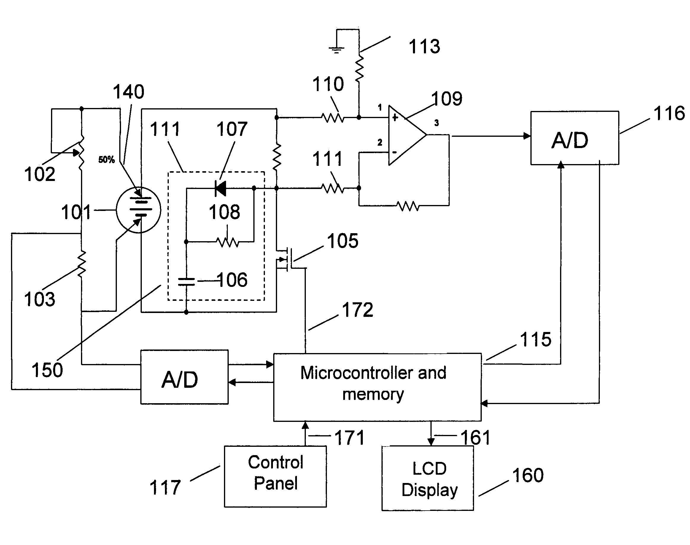
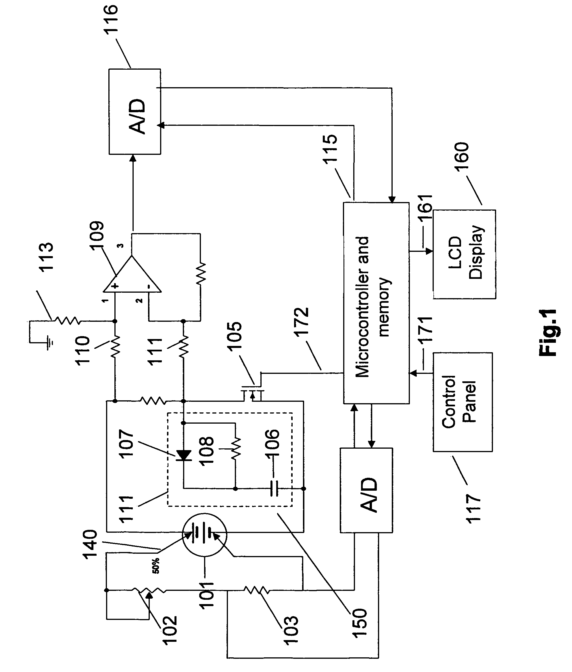
[0039]The following describes an embodiment of the present invention. Referring to FIG. 1, a block circuit diagram 100 of a relevant portion of a testing apparatus is shown. In order to measure its potential voltage, the tested battery 101 is connected serially, by a pair of Kelvin clamps 140, to resistors 102, and 103. For receiving an accurate measurement, the voltage is divided between the resistors. Resistor 102 has varying resistance while resistor 103 has a constant resistance. Another pair of Kelvin clamps 150, connect the tested battery 101 to resistor 104, which is used as a measuring resistive shunt, and to power switch 105 (may be a MOSFET or a IGBT transistors). Snubber circuit 150 is connected in parallel to switch 105. The snubber circuit 150 comprises: a capacitor 106 connected serially to a parallel connected diode 907 and resistor 108.

[0040]A differential amplifier 109, used for measuring the current in the circuit 100, is connected by resistors 110 and 111 to shunt...


PUM

PropertyMeasurementUnit
time periodaaaaaaaaaa
timeaaaaaaaaaa

Abstract

According to this invention a battery testing device is provided. Such device activates a shortening between the battery poles using a predefined electronic circuit (in order to maximize the battery's energy potential) for a time period of 10-50 μsec. In a subsequent time period of ˜100-200 μsec, the loading is slowly decreased until the voltage returns to an open circuit voltage UOC. During the testing process, the voltage and the battery current are measured. The measurements are stored at the device database, to be later used in an algorithm for checking battery conditions.

Description

BACKGROUND OF INVENTION[0001]The present invention relates to electronic battery testing and measuring. More specifically the present invention relates to a method and apparatus for measuring and checking parameters such as voltage, cold cranking amperage (CCA), state of charge (SOC) and state of health (SOH) of a standard battery.[0002]Different methods were developed over the years in order to measure the power status and condition of lead acid batteries, such as those used in Vehicles, UPS systems, and in solar energy arrangements etc.[0003]One such measuring method is taught in U.S. Pat. No. 5,598,098, wherein battery condition and measurement parameters are obtained through a correlation analysis. The method is based on battery conductance measurement.[0004]Another prior art method (U.S. Pat. No. 6,441,585) uses measurements of impedance or admittance. Another, uses the measurement of OCV (U.S. Pat. No. 6,366,054). Still another prior art measurement method uses special battery...

Claims


Application Information

Patent Timeline
Patent Type & Authority Patents(United States)
IPC IPC(8): G01N27/416G01R31/36
CPCG01R31/3651G01R31/3624G01R31/367G01R31/3842
Inventor AVERBUCH, MOSHE
Owner BATTERY CONTROL CORP
Why Eureka
Try Eureka