
Lane-departure warning system with differentiation between an edge-of-lane marking and a structural boundary of the edge of the lane

a technology of lane departure warning and structural boundary, which is applied in the direction of television system, process and machine control, instruments, etc., can solve the problems of not being able to bring about automatic braking or steering intervention, not being able to reliably and adequately warn, and only having one image-transmitting sensor

Inactive Publication Date: 2008-08-12
DAIMLER AG
View PDF22 Cites 58 Cited by
  • Summary
  • Abstract
  • Description
  • Claims
  • Application Information

AI Technical Summary

Problems solved by technology

In such a case, the warning device may both cause a warning signal to be output and bring about an automatic braking or steering intervention.
However, lane-departure warning systems which are equipped with only one image-transmitting sensor are not capable of differentiating between edge-of-lane markings and a structural boundary at the edge of the lane, for example kerb stones, crash barriers or concrete walls so that in particular in sections of a road in which no edge-of-lane markings are provided and a structural boundary forms the edge of the lane these do not reliably and adequately warn of a risk of departure of the motor vehicle from the lane.
If, for example, a kerb is detected by such a lane-departure warning system as an edge-of-lane marking, damage to the tyres or the rims of the motor vehicle already occurs if a warning of a risk of departure of the motor vehicle from the lane is not issued until the motor vehicle enters into contact with or passes beyond the supposed marking.
This damage and the associated hazard situation, together with the resulting loss of confidence of the driver of the motor vehicle in the reliability of the lane-departure warning system, have an adverse effect on the road safety of the motor vehicle.
Furthermore, as a result of faults in the evaluation of the data supplied by the image-transmitting sensor incorrect warnings may easily occur, in particular in regions without edge-of-lane markings.

Method used


Image

  • Lane-departure warning system with differentiation between an edge-of-lane marking and a structural boundary of the edge of the lane
  • Lane-departure warning system with differentiation between an edge-of-lane marking and a structural boundary of the edge of the lane

Examples


Embodiment Construction

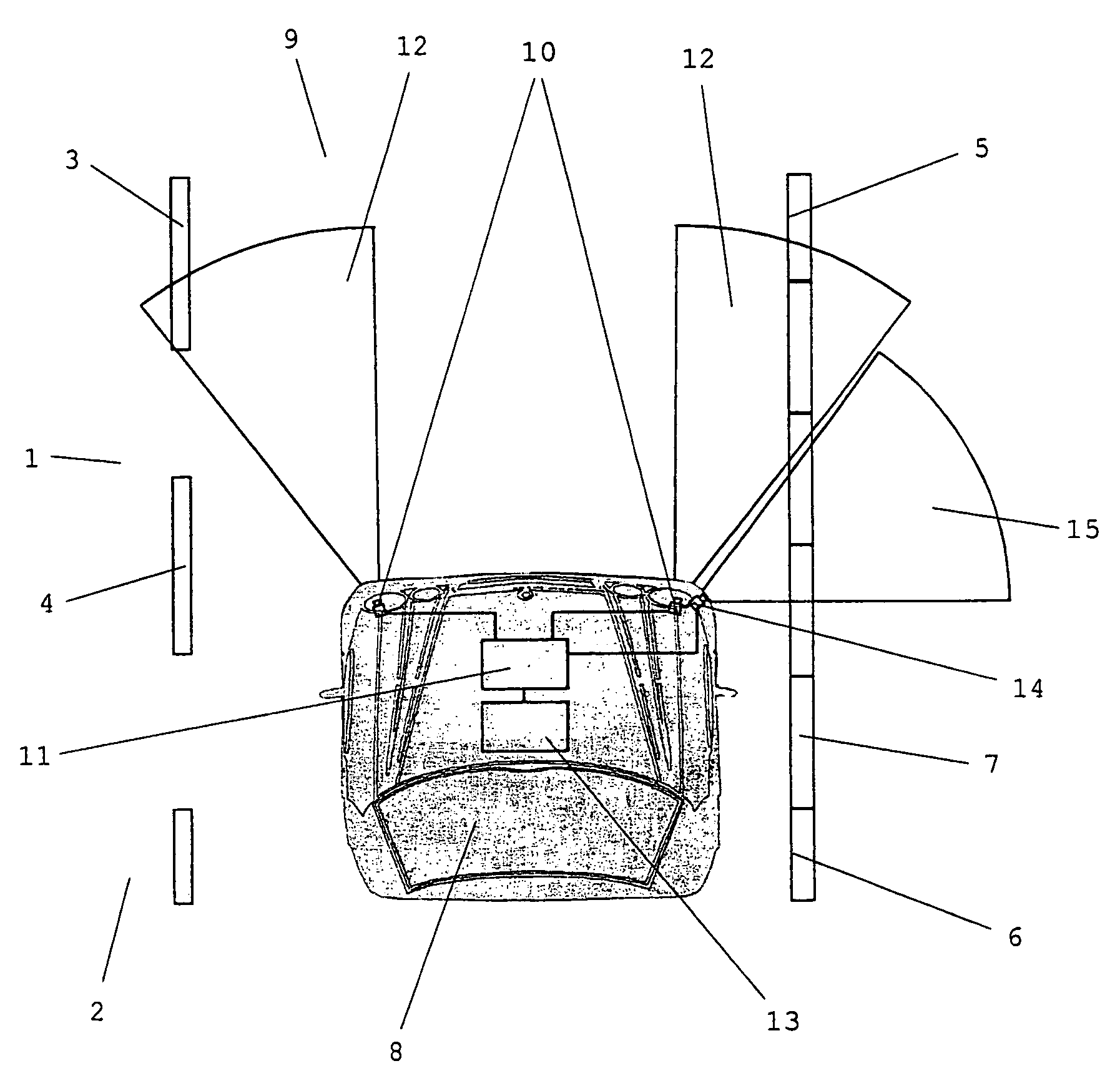
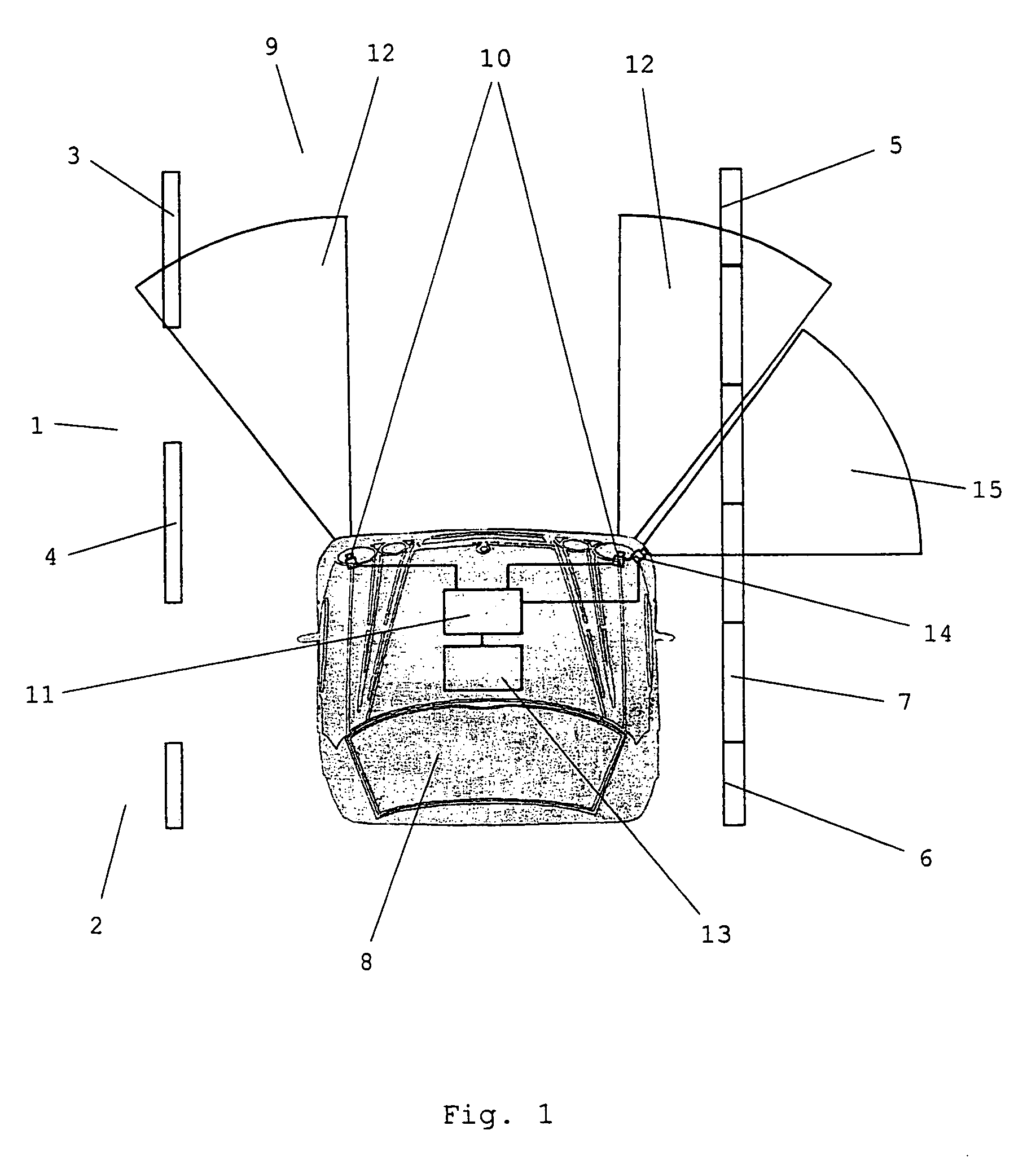
[0017]The object is achieved in a device of the generic type mentioned at the beginning in that, in addition to the image-transmitting sensor, at least one distance-transmitting sensor is connected to the evaluation device, with which sensor the distance from objects which are elevated with respect to the surface of the lane can be determined in the region of the edge of the lane, in particular a structural boundary of the edge of the lane, and / or with which the distance from a border at which the surface of the lane ends in the region of the edge of the lane and drops away to a piece of lower surrounding land, such as, for example, in the case of elevated asphalt coverings or trenches or water channels which run adjacent to the edge of the lane and in parallel with the lane, can be determined.

[0018]The driver assistance device according to the invention has, in comparison with the prior art, the advantage that, as a result of the additional, distance-transmitting sensor, an object ...


PUM


Abstract

A driver assistance device for warning a driver of a motor vehicle of a risk of departure from the lane or from the lane is described, having at least one image-transmitting sensor, an evaluation device, connected to the image-transmitting sensor, for detecting edge-of-lane and / or lane markings and / or edges of lanes in the area sensed by the image-transmitting sensor, and a warning device which is connected to the evaluation device, in which driver assistance device in addition at least one distance-transmitting sensor is connected to the evaluation device, with which sensor the distance from objects which are elevated with respect to the surface of the lane can be determined in the region of the edge of the lane, in particular of a structural boundary of the edge of the lane.

Description

BACKGROUND OF THE INVENTION[0001]1. Field of the Invention[0002]The invention relates to a driver assistance device for warning a driver of a motor vehicle of a risk of departure from the road or from the lane.[0003]2. Related Art of the Invention[0004]Modern driver assistance devices for warning a driver of a motor vehicle of a risk of departure from the lane or the lane, known as a lane-departure warning system, contribute considerably to increasing road safety through the detection of hazardous situations by outputting acoustic or optical warning signals when there is the risk of departure from the lane or the lane.[0005]Contemporary lane-departure warning systems usually have an image-transmitting sensor for lane detection and lane detection, which sensor is connected to an evaluation device which detects lane markings, edge-of-lane markings and, in some cases, structural boundaries of the edges of the lane as edge-of-lane markings in the area sensed by the image-transmitting se...

Claims


Application Information

Patent Timeline
Patent Type & Authority Patents(United States)
IPC IPC(8): B60Q1/00G05D1/00G05D1/02G06F17/10G08G1/00G08G1/04G08G1/14G08G1/017H04N7/00H04N7/18B60R21/00G08G1/16
CPCB60Q9/008
Inventor GERN, AXELLOTTER, ALFREDMOEBUS, RAINEROLTMANN, VOLKERWOLTERMANN, BERNDZOMOTOR, ZOLTAN
Owner DAIMLER AG
Learn More