System and method for asynchronous wireless positioning by ordered transmission

a wireless positioning and ordered transmission technology, applied in direction finders using radio waves, instruments, reradiation, etc., can solve the problems of inability to achieve high-precision positioning, wired signal transfer errors, and difficulty in putting the method to practical use, so as to achieve accurate indirect time synchronization and high-precision position tracking

Active Publication Date: 2008-08-12
KOREA ELECTROTECH RES INST
View PDF33 Cites 11 Cited by
  • Summary
  • Abstract
  • Description
  • Claims
  • Application Information

AI Technical Summary

Benefits of technology

[0013]Accordingly, the present invention has been made to solve the above-mentioned problems occurring in the prior art, and an object of the present invention is to provide a wireless positioning system and method that can perform high-precision position tracking by minimizing errors through a proposed method for accurately obtaining indirect time synchronization without the necessity of time synchronization. In applying the present invention, the use of UWB pulses as wireless signals enables a high-precision position tracking that makes the best use of the advantages of the UWB-pulses.
[0014]Another object of the present invention is to provide a wireless positioning system and method that can use a target device of a simple structure without the necessity of a complicated operation process in the target device, perform low-power operation through simplification of the construction of the target device and minimization of the number of signal transmissions, and achieve a precise position tracking.
[0015]Still another object of the present invention is to provide a wireless positioning system and method that can perform a more accurate positioning by making it possible to detect a ToA (Time of Arrival) and a TDoA (Time Difference of Arrival) through the pulse transmission / reception even if the synchronization among beacon devices is not provided and the accurate distance information about the wave propagation paths is not known.

Problems solved by technology

However, in the currently required systems of a high precision, e.g., having time resolutions below nanosecond, PLL (Phase Lock Loop) adjustment errors for obtaining the time synchronization, wired signal transfer errors, etc., become greater than the pulse durations if the systems are constructed so that they require the time synchronization among the beacon devices as in the prior art.
This causes severe problems due to the synchronization errors when links among the beacon devices for the synchronization are made through not only wireless paths but also wire paths.
As a consequence, if the existing systems are applied as they are, it becomes impossible to achieve a high-precision positioning that makes the best use of the advantages of the UWB pulses having the extremely short durations.
However, because this method requires a GPS receiver, etc., (provided in the respective beacon device) the system is complicated and thus it is difficult to put the method to practical use.
Additionally, because the system using the GPS has limited precision of time synchronization, it is impossible to achieve the wireless positioning of high precision below several meters through this method.
However, this method has the problems in that because the target device should serve as a signal receiver and processor, the structure of the target device becomes very complicated, and thus the application of this method is limited.
However, this assumption may not be satisfied because the actual wave propagation paths may be complicated according to diverse environmental variables such as the curved surface of the earth and so on, and thus the synchronization among the beacon devices is ultimately required in order to heighten the precision of positioning even though this method is used.
In addition, the target device (or tag) that is an object of the position tracking is generally a portable simplified individual device to which the power supply is not easy.

Method used


Image

  • System and method for asynchronous wireless positioning by ordered transmission
  • System and method for asynchronous wireless positioning by ordered transmission
  • System and method for asynchronous wireless positioning by ordered transmission

Examples


Embodiment Construction

[0049]Hereinafter, preferred embodiments of the present invention will be described with reference to the accompanying drawings. In the following description and drawings, the same reference numerals are used to designate the same or similar components, and so repetition of the description on the same or similar components will be omitted.

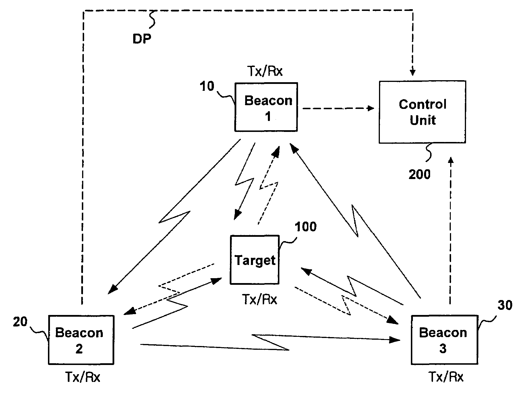
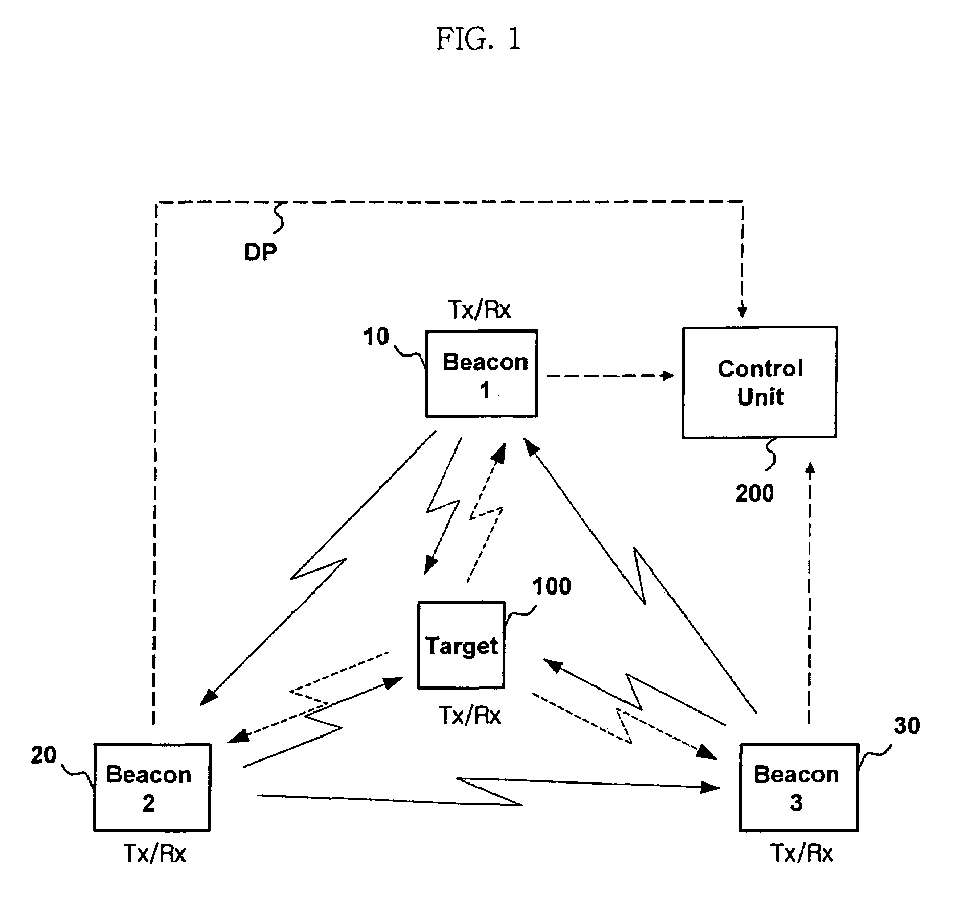
[0050]FIG. 1 is a schematic view illustrating a wireless positioning system according to the present invention. The system according to the present invention includes a plurality of beacon devices including a first beacon device 10, a second beacon device 20 and a third beacon device 30, a control unit 200 for receiving data from the beacon devices, and a target device (or tag) 100 that is an object of a position tracking. Here, wire data communication paths may not be provided among the beacon devices, and all data transmission / reception may be performed by wireless.

[0051]The control unit 200 refers to a main processing device that finally determi...


PUM


Abstract

Disclosed is a wireless positioning system and method that can perform a high-precision position tracking. The wireless positioning system includes a target device that is an object of wireless positioning, beacon devices and a processing unit. The beacon devices transmits wireless signals and sense reception time points of the wireless signals transmitted from the other beacon devices and the target device and received at time points after the transmission of the wireless signal. The target device receives the wireless signal transmitted from at least one of the beacon devices, and then transmits the wireless signal to the beacon devices. The processing unit obtains the position of the target device by calculating distances between the beacon devices and the target device using information about the reception time points of the wireless signals sensed by the respective beacon devices.

Description

BACKGROUND OF THE INVENTION[0001]1. Field of the Invention[0002]The present invention relates generally to wireless positioning techniques, and more particularly to a system and method for determining the position of a target device by ordered transmission of wireless signals even without distance information and pre-synchronization among beacon devices. The beacon device is a device which is the basis of determining the position of the target device and the position of which is previously known before the process of determining the poison of the target device is performed.[0003]2. Description of the Prior Art[0004]Recently, as the advantages of UWB (Ultra Wideband) wireless technologies are being watched, researches for short-distance high-precision wireless positioning systems have actively been in progress as one of applications of UWB pulses having extremely short durations.[0005]Because the UWB pulses have the extremely short durations below nanosecond, they have been applied t...

Claims


Application Information

Patent Timeline
Patent Type & Authority Patents(United States)
IPC IPC(8): G01S3/02G01S1/24G01S3/28G01S13/87G01S19/10G01S19/21G01S19/46H04Q7/20
CPCG01S13/878G01S1/024G01S13/76
Inventor CHOI, SUNGSOOOH, HUI-MYUNGKIM, KWAN-HOSHIN, YOANLEE, WON CHEOLPARK, WOON-YONGPARK, YOUNGJIN
Owner KOREA ELECTROTECH RES INST
Why Eureka
Try Eureka