Umbrella with rotation mechanism

a technology of rotating mechanism and umbrella, which is applied in the direction of umbrellas, mechanical devices, machine supports, etc., to achieve the effect of flexible positioning

Active Publication Date: 2008-08-19
MA
View PDF32 Cites 52 Cited by
  • Summary
  • Abstract
  • Description
  • Claims
  • Application Information

AI Technical Summary

Problems solved by technology

These and other disadvantages of prior rotating umbrellas have created a need for an improved shelter structure and ways to alter the position of such a structure as conditions change.

Method used


Image

  • Umbrella with rotation mechanism
  • Umbrella with rotation mechanism
  • Umbrella with rotation mechanism

Examples


Embodiment Construction

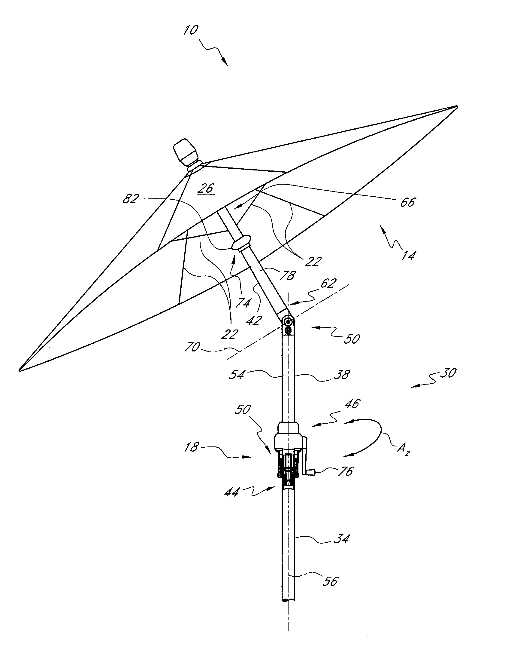
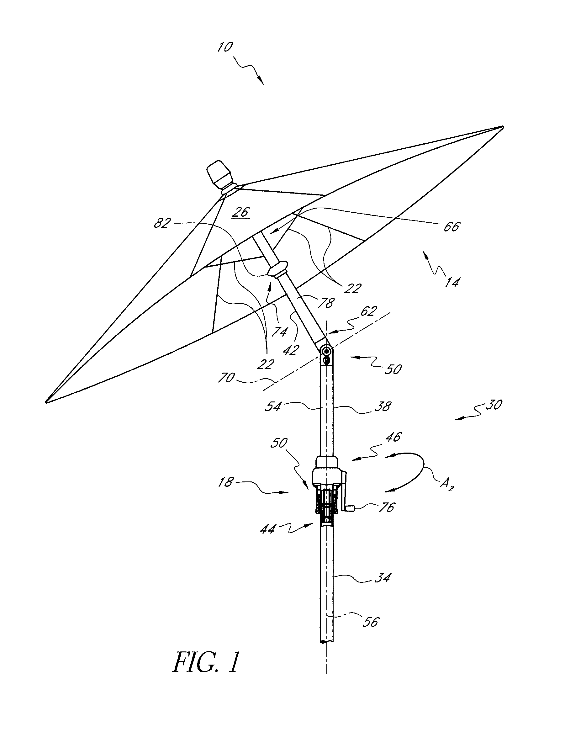
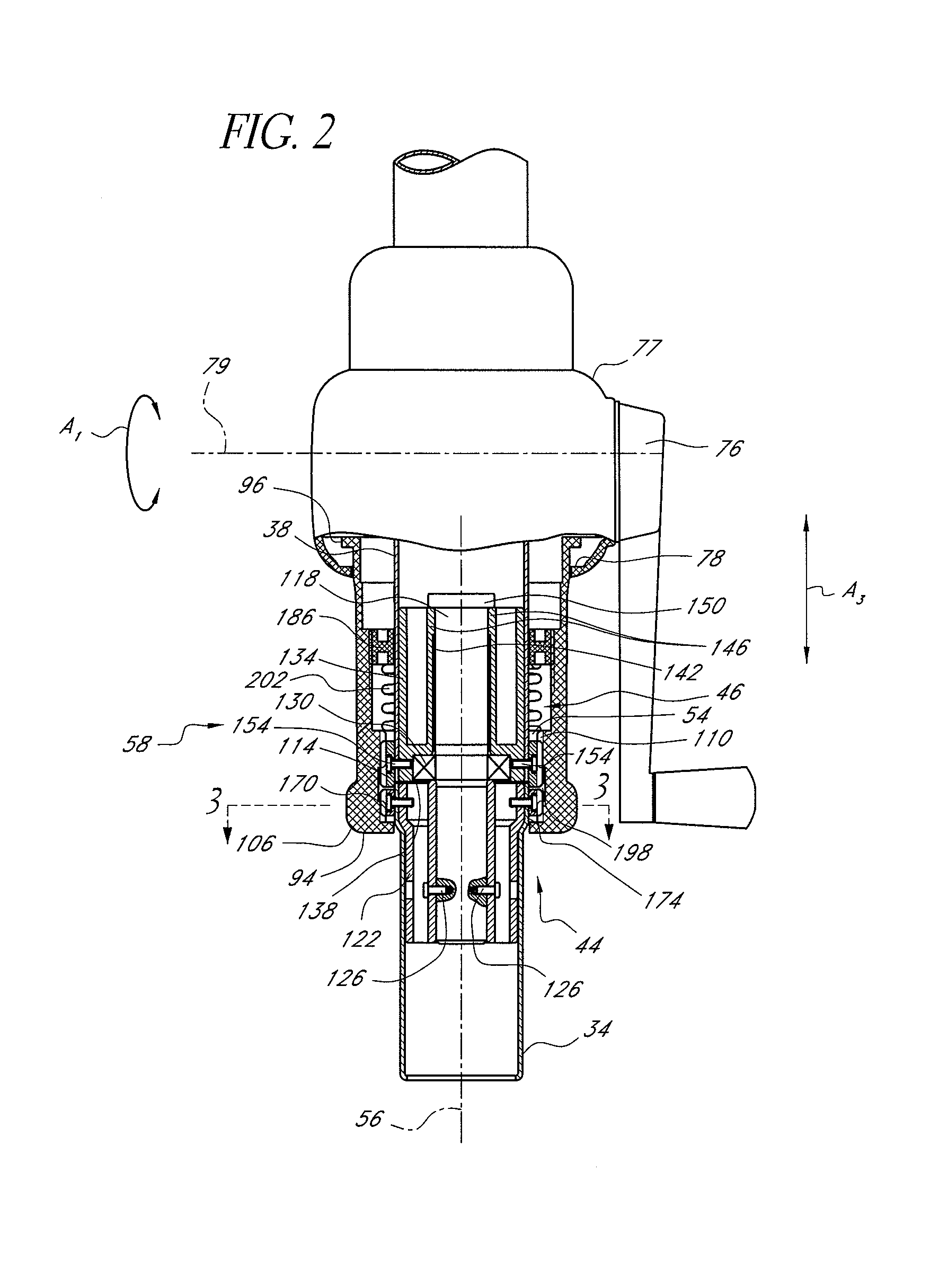
[0027]FIG. 1 is a plan view of one embodiment of an umbrella 10 that has a canopy 14 and a rotation mechanism 18. As discussed more fully below, the rotation mechanism 18 advantageously is arranged to transmit a torque directly to a first portion of the umbrella 10 relative to a second portion thereof to impart relative motion therebetween, e.g., rotation of an upper portion relative to a lower portion. Additionally, the rotation mechanism 18 advantageously is located beneath a second mechanism that opens and closes the canopy 14. As discussed further below, the second mechanism can be one that is driven by a crank. These and other features discussed below provide a simple structure compared to prior designs and provide flexible positioning at any desired tilt angle within a large number of vertical planes extending through the umbrella 10.

[0028]The canopy 14 can take any suitable or conventional form. In one embodiment, the canopy 14 includes a frame 21 comprising a plurality of ri...


PUM


Abstract

An umbrella is provided that includes a lower pole portion, an upper pole portion, a canopy coupled with the upper pole portion, a crank, and a rotation mechanism. The upper pole portion is rotatably coupled with the lower pole portion. The crank is configured to articulate the canopy. The rotation mechanism is configured to apply a force to the upper pole portion. The rotation mechanism is at least partially located between the crank and the lower pole portion.

Description

RELATED APPLICATION[0001]This application claims priority under 35 U.S.C. §119(a) to Chinese parent Application No. 200410025699.3, filed Jun. 24, 2004, and to Chinese Utility Model No. 200420023521.0, filed Jun. 8, 2004.BACKGROUND OF THE INVENTION[0002]1. Field of the Invention[0003]This application relates to a structure for providing shelter from the elements, such as an umbrella, and mechanisms for altering where such shelter is provided, particularly as conditions change.[0004]2. Description of the Related Art[0005]Umbrellas have been developed to provide shelter from the elements and are particularly useful in outdoor seating areas, such as on a backyard patio. Typically, an umbrella comprises a support pole and a retractable canopy positioned at the top of the pole for providing shade. Basic umbrellas have a canopy fixed in a plane perpendicular to the axis of the support pole. However, such umbrellas have limited ability to place the shade where it is desired. The position o...

Claims


Application Information

Patent Timeline
Patent Type & Authority Patents(United States)
IPC IPC(8): A45B17/00A45B25/14A45B3/00A45B5/00A45B11/00A45B25/00F16M11/04F16M13/00
CPCA45B17/00
Inventor MA, OLIVER JOEN-AN
Owner MA
Why Eureka
Try Eureka