Electromagnetic rotary drive

a technology of rotary drive and magnetomotive force, which is applied in the direction of magnetic circuit rotating parts, magnetic circuit shape/form/construction, liquid fuel engines, etc., can solve the problems of inability to realize high magnetomotive force, additional costs, and metals represent a substantial cost factor, so as to reduce the number of position sensors in the stator

Active Publication Date: 2017-01-12
LEVITRONIX
View PDF22 Cites 27 Cited by
  • Summary
  • Abstract
  • Description
  • Claims
  • Application Information

AI Technical Summary

Benefits of technology

[0008]A further advantage of the principle of the bearingless motor in pumping or mixing applications results from the design of the rotor as an integral rotor which is both the rotor of the electromagnetic drive and the rotor of the pump or mixer. In addition to the contactless magnetic support, the advantage results here of a very compact and space-saving configuration.
[0030]It is preferred for the generation of the electromagnetic fields or of the rotating fields that a coil is arranged as a winding on each upper stator pole and at each lower stator pole, wherein a respective separate power amplifier is provided for each coil with which the coil current or the coil voltage for the coil can respectively be regulated independently of the coil currents or of the coil voltages of the other coils. This measure is particularly advantageous to exert both a torque on the rotor by the stator and also a shear force, which can be set as desired, in the radial direction by which the radial position of the rotor—that is its position in the plane perpendicular to the desired axis of rotation—can be actively magnetically regulated. The independent control capability of each coil additionally makes it possible that the position of the rotor with respect to tilts against the desired axis of rotation (two degrees of freedom) can be actively magnetically regulated by the cooperation of the upper stator part and of the lower stator part.

Problems solved by technology

Such single-use applications today frequently replace processes in which all those components which come into contact with the substances to be treated in the process once had to be cleaned and sterilized in a complex and / or expensive manner, for example by means of steam sterilization, due to the very high purity demands.
However, such metals represent a substantial cost factor due to their comparatively small occurrence and due to their complex and / or expensive mining and processing.
In addition, the waste disposal of such permanent magnets after a single use, for example, is frequently also associated with problems or a high effort under technical environmental aspects, whereby additional costs arise.
If the stator is excited as customary solely by windings, such a high magnetomotive force is impossible to realize in the mostly tight construction space of the stator with reasonable dimensions.

Method used


Image

  • Electromagnetic rotary drive
  • Electromagnetic rotary drive
  • Electromagnetic rotary drive

Examples


first embodiment

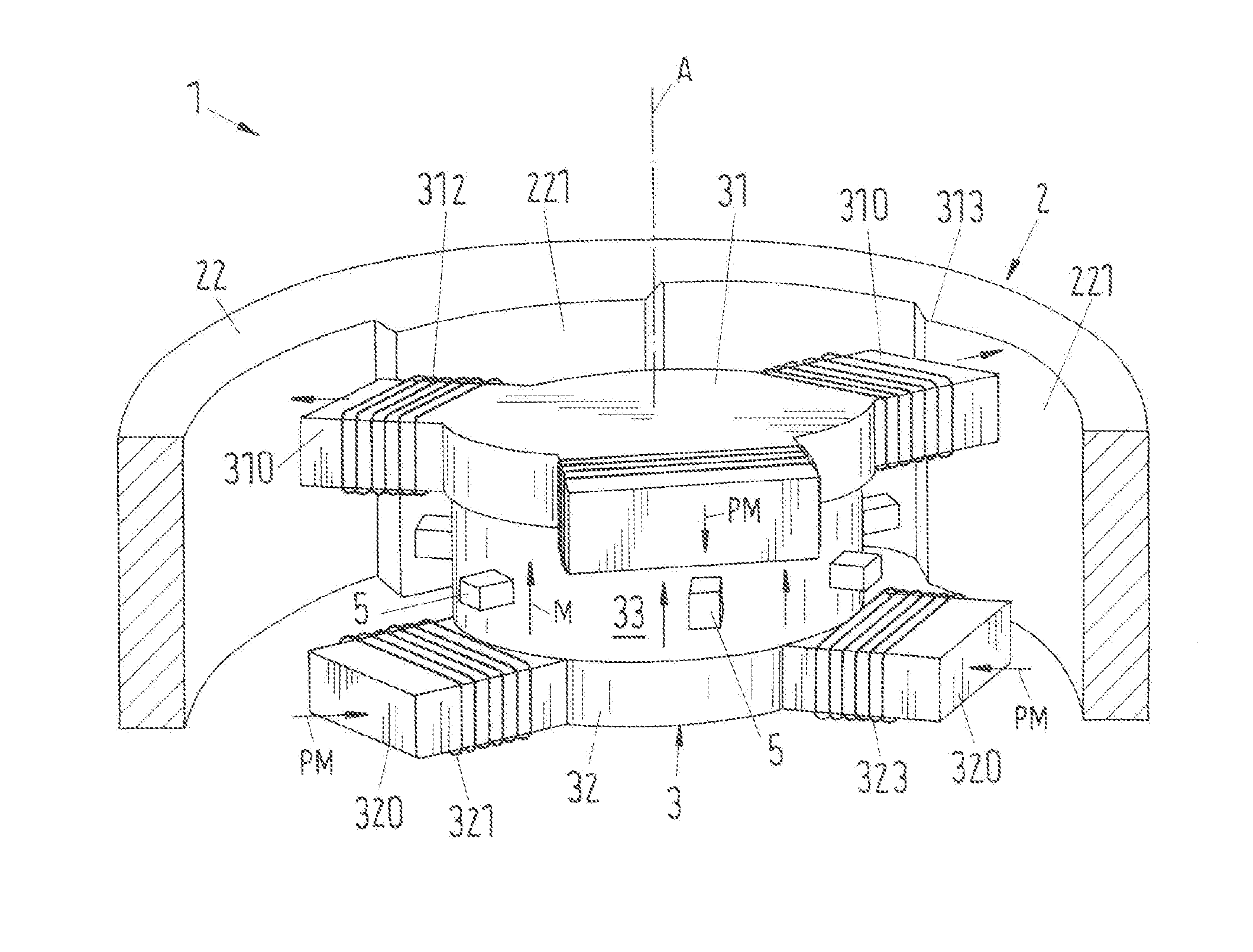
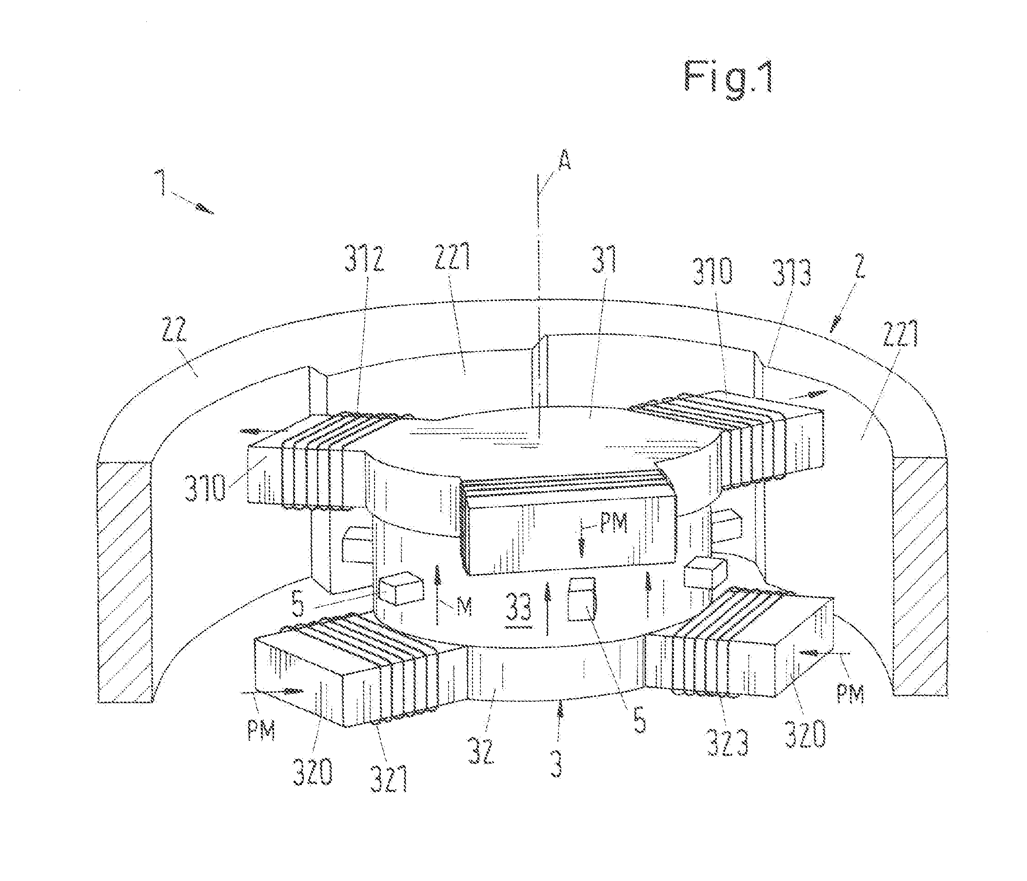
[0062]FIG. 1 shows in a perspective sectional representation an electromagnetic rotary drive in accordance with the invention which is designated as a whole by the reference numeral 1. The rotary drive 1 is configured in accordance with the principle of the bearingless motor and comprises a rotor 2 which is magnetically contactlessly drivable and which is free of coils as well as a stator 3 which is configured as a bearing and drive stator by which the rotor 2 can be magnetically contactlessly driven about a desired axis of rotation A in the operating state and can be magnetically contactlessly supported with respect to the stator 3. In the embodiment described here, the stator 3 is arranged inwardly disposed with respect to the rotor 2.

[0063]In the following, that axis of rotation is called the desired axis of rotation A about which the rotor 2 rotates when it is in a centered position with respect to the stator 3. The rotor 2 is then centered in a plane which is perpendicular to t...

second embodiment

[0139]In the second embodiment shown in FIG. 22, the electromagnetic rotary drive 1 configured as a pumping or mixing apparatus comprises a flexible mixing tank 71 for receiving the substances to be mixed which is manufactured from a plastic and which is only indicated in FIG. 22. The mixing tank 71 is preferably a flexible pouch, for example a plastic sack or a sack of a synthetic material, which can be folded together so that is takes up as little space as possible during storage. The mixing tank 71 is placed into a support tank 51 which is likewise only indicated in FIG. 22 and which supports the mixing tank 71.

[0140]The mixing tank 71 has in its base region a substantially cylindrical bucket 75 which extends in the inner space of the mixing tank 71 and is arranged at the center of the base region. The cylindrical bucket 75 is preferably stable in shape and produced from a plastic. It can also be formed in the form of a flexible hose, for example.

[0141]The rotor 2 which comprises...

third embodiment

[0166]It is in particular preferred in the third embodiment that each of the coils of the lower stator part 32 and each of the coils of the upper stator part 31 can be controlled separately so that the rotor 3 can be actively magnetically regulated with respect to tilts toward the radial plane (two degrees of freedom). It is understood that the two stator parts 31, 32 can also have more than three coils and poles, in particular also four, five or six coils and upper poles 310 and lower poles 320.

[0167]It is understood that more than two impellers 21, 25 can also be provided on the rotor.

[0168]FIG. 24 shows in a perspective sectional representation a fourth embodiment of the rotary drive 1 in accordance with the invention which is integrated into a mixing apparatus. In the following, only the differences from the above-described first, second and third embodiments will be looked at. The reference numerals in particular have the same meaning as has already been explained in connection...


PUM


Abstract

An electromagnetic rotary drive includes a magnetically contactlessly drivable rotor free of coils, and a stator configured as a bearing and drive stator configured to drive the rotor magnetically and contactlessly about an axis of rotation. The rotor is capable of being supported magnetically contactlessly with respect to the stator in an operating state. The stator includes an upper stator part having a plurality of pronounced upper poles configured to carry upper windings and a lower stator part having a plurality of pronounced lower poles configured to carry lower windings. The upper stator part and the lower stator part are arranged spaced apart from one another with respect to an axial direction. A permanent magnet is disposed between the upper stator part and the lower stator part.

Description

CROSS-REFERENCE TO RELATED APPLICATIONS[0001]This application claims priority to EP Application No.: 15175531.1, filed Jul. 6, 2015, the contents of which is hereby incorporated herein by reference.BACKGROUND[0002]Field of the Invention[0003]The invention relates to an electromagnetic rotary drive.[0004]Background of the Invention[0005]Electromagnetic rotary drives are known which are configured and operated in accordance with the principle of a bearingless motor. The term bearingless motor in this respect means an electromagnetic rotary drive in which the rotor is supported completely magnetically with respect to the stator, with no separate magnetic bearings being provided. For this purpose, the stator is configured as a bearing and drive stator which is therefore both the stator of the electric drive and the stator of the magnetic support. A rotating magnetic field can be produced using the electrical windings which, on the one hand, exerts a torque onto the rotor which effects i...

Claims


Application Information

Patent Timeline
Patent Type & Authority Applications(United States)
IPC IPC(8): H02K7/09H02K3/18H02K1/22H02K1/14H02K1/17A61M60/10A61M60/237A61M60/422A61M60/508A61M60/818
CPCH02K7/09H02K1/146H02K3/18H02K1/22H02K1/17F04D29/058F16C32/0465H02K19/103F04D3/00F04D13/0673F04D25/0613F04D29/048F16C32/0446F16C32/0457F16C32/0485F16C32/0489A61M60/422F04D13/064B01F33/4535A61M60/237A61M60/508A61M60/10A61M60/818
Inventor SCHOB, RETOHUGEL, JORGHOLENSTEIN, THOMAS
Owner LEVITRONIX
Why Eureka
Try Eureka