Electromagnetic motor with flux stabilization ring, saturation tips, and radiator

a technology of flux stabilization ring and electric motor, which is applied in the direction of dynamo-electric machines, transducer details, electrical transducers, etc., can solve the problems of generating and discharging heat, affecting the operation of speakers, and limited tolerance of various internal components

Inactive Publication Date: 2004-08-10
HARMAN INT IND INC
View PDF56 Cites 26 Cited by
  • Summary
  • Abstract
  • Description
  • Claims
  • Application Information

AI Technical Summary

Problems solved by technology

One common problem associated with electromagnetic transducers is the generation and dissipation of heat.
The tolerance of the various internal components is limited by the thermal breakdown of those various components.
If the internal components become too hot, the adhesives used to contact the components together, or the components themselves, will melt, resulting in a breakdown in the operation of the speaker.
Thus, the power handling capacity of a motor is limited by its ability to tolerate heat.
Another problem associated with heat is temperature-induced resistance, commonly referred to as power compression.
At higher temperatures, power input is converted mostly into additional heat rather than sound, thereby seriously limiting motor efficiency.
Another, problem is that the magnet in the transducer creates a static magnetic field, and thi

Method used


Image

  • Electromagnetic motor with flux stabilization ring, saturation tips, and radiator
  • Electromagnetic motor with flux stabilization ring, saturation tips, and radiator
  • Electromagnetic motor with flux stabilization ring, saturation tips, and radiator

Examples


Embodiment Construction

This description is not to be taken in a limiting sense, but is made merely for the purpose of illustrating the general principles of the invention. The section titles and overall organization of the present detailed description are for the purpose of convenience only and are not intended to limit the present invention.

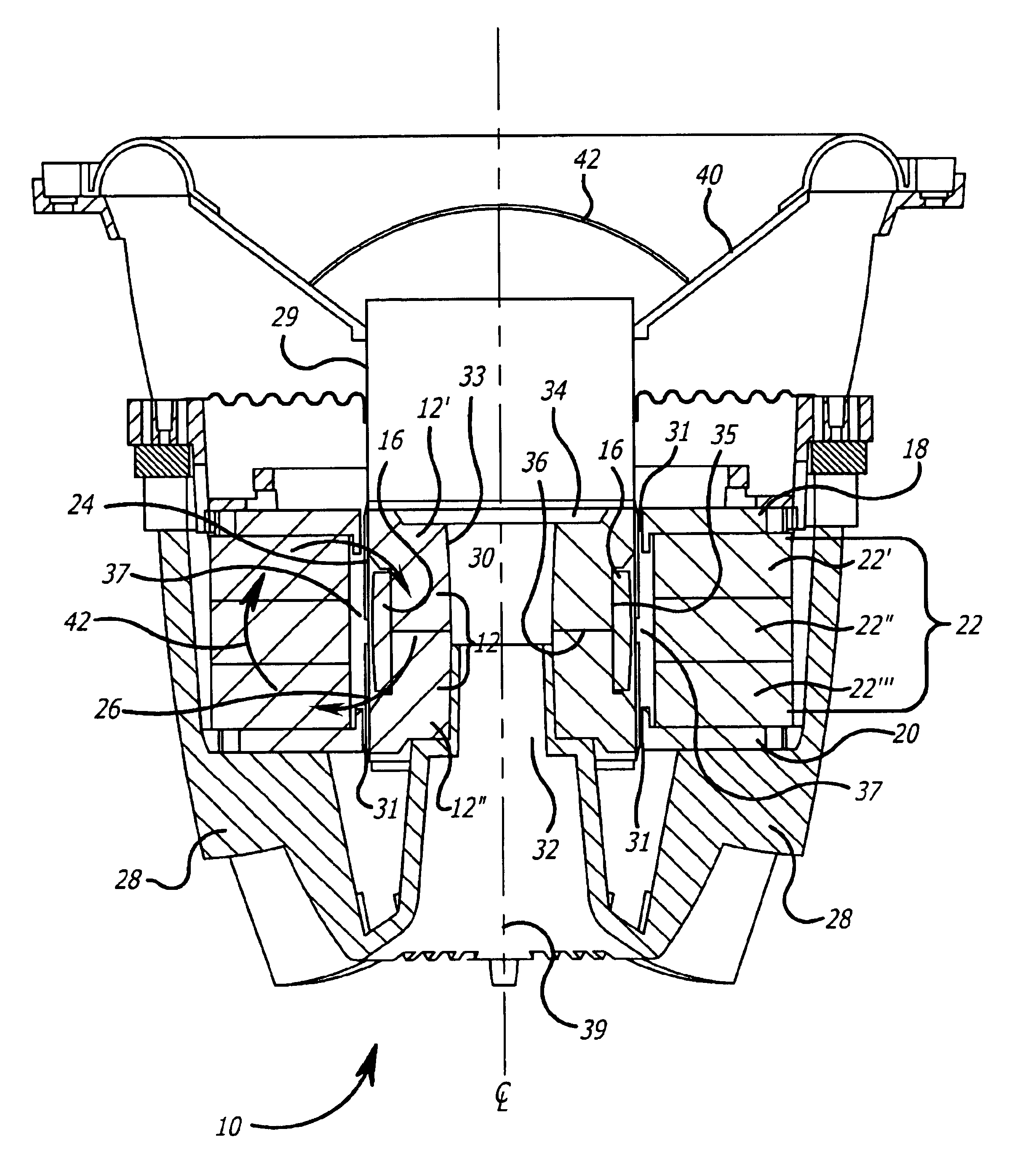
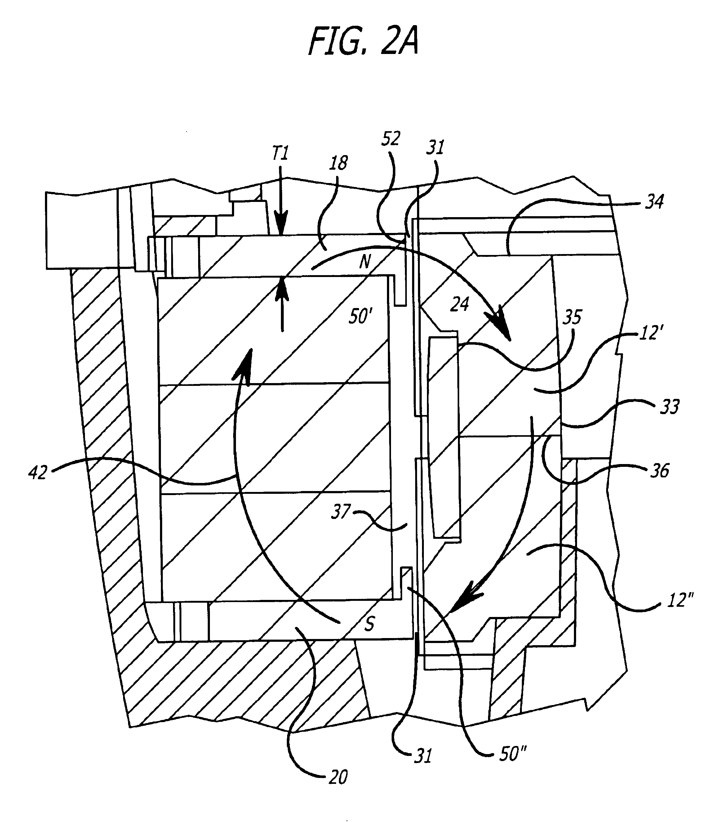
FIG. 1 illustrate by way of example one embodiment of an electromagnetic drive motor assembly (EDMA) 10 that includes an inner flux return assembly 12 including an upper pole piece 12' and a lower pole piece 12"; a flux stabilization ring 16 wrapped around the inner flux return assembly 12; a first voice coil 24 and a second voice coil 26 wrapped around a cylinder 29; an outer magnet assembly 22', 22", and 22'" is between a top plate 18 and a bottom plate 20; and the voice coils 24 and 26 are disposed in the pair magnet gaps 31 that are formed between the top plate 18 and the inner flux return assembly 12, and the bottom plate 20 and the inner flux return assembly 12 ...


PUM


Abstract

The present invention provides an electromagnetic drive motor assembly (EDMA) that has an inner flux return assembly formed from an upper pole piece and a lower pole piece oppositely disposed relative to each other along the center of the EDMA. An annularly positioned conductive ring (or flux stabilization ring) encircles the inner flux return assembly, concentrically in contact with the outside of the inner flux return assembly. Along the exterior side of the flux return pieces, is a magnet that is between a top plate and a bottom plate. Each plate contacts with the magnet to form a magnetically conductive system. A magnetic gap is formed in between the inner flux return assembly and the top and bottom plates. Disposed within the magnetic gap is a dual coil wound around a cylinder. The dual coil includes a first coil portion and a second coil portion. To minimize the modulation, the top and bottom plates may be saturated and plate tips may be provided near the magnetic gap. And to dissipate heat away from the magnetic gap, a thermal radiating conductive ring may be provided as well.

Description

1. Field of the InventionThis invention relates generally to an electromagnetic drive motor assembly (EDMA). More particularly, the invention relates to a design of an EDMA that has dual coils positioned within a magnetic gap formed by a flux return assembly inside and an outside assembly of top and bottom plates sandwiching a permanent magnetic material. Enclosing the flux return assembly is a flux stabilization ring.2. Description of the Related ArtDual coil, dual gap electromagnetic motors or transducers have existed for many years, and recently they have been used more widely in the field of speaker design. Typically, an electromagnetic motor uses magnets to produce magnetic flux in an air gap. These magnets are typically permanent magnets, used in a magnetic circuit of ferromagnetic material to direct most of the flux produced by the permanent magnet through the components of the motor and into the air gap.In one prior art transducer, a coil is placed in an air gap with its con...

Claims


Application Information

Patent Timeline
IPC IPC(8): H02K41/035H04R9/02H04R9/00H02K9/22H02K16/00H02K16/02
CPCH02K41/0356H04R9/025H02K9/22H02K16/02H04R9/022H04R2209/041H02K9/223
Inventor MORO, JERRYBUTTON, DOUGLAS J.
Owner HARMAN INT IND INC
Why Eureka
Try Eureka