Compressor including pressure relief mechanism

a pressure relief mechanism and compressor technology, applied in the field of compressors, can solve the problems of significantly lowering the refrigerating performance of the refrigerating circuit, affecting the operation of the compressor, so as to prevent the improper operation of the compressor and prevent the fluid from flowing

Active Publication Date: 2008-08-19
SANDEN CORP
View PDF40 Cites 9 Cited by
  • Summary
  • Abstract
  • Description
  • Claims
  • Application Information

AI Technical Summary

Benefits of technology

[0016]An object of the present invention is to provide a compressor which prevents an improper operation of a relief valve and prevents working fluid and lubricating oil therein from being undesirably lost.
[0022]According to the compressor of the present invention mentioned above, the relief device is located in a downstream side of the separating device. When the impact pressure exceeding the relief pressure of the relief device is instantaneously generated in the discharge chamber, the impact pressure is therefore attenuated lower than the relief pressure before the impact pressure is propagated to the relief device. As a result, the improper operation of the relief device caused by the impact pressure can be effectively lowered.
[0024]On the other hand, the working fluid introduced to the discharge chamber from the intake chamber via the compression chamber contains the lubricating oil sufficiently, and the lubricating oil in the working fluid is effectively used for lubricating of the compressor and sealing of the compression chamber in the compressor.
[0025]The relief device can include a relief valve located in a downstream side of the discharge path. In this case, it is preferable that the relief valve is located near the outlet port. When the relief valve is located near the outlet port as mentioned above, it is possible to secure length of the discharge path from the discharge chamber to the relief valve long, and the impact pressure can be effectively attenuated.
[0027]The housing can further has an adapter pipe forming the outlet port and provided with the relief valve. In this case, it is possible to further extend the length of the discharge path from the discharge chamber to the relief valve.
[0031]According to the separating device mentioned above, it is possible to secure the separating chamber without enlarging the housing.

Problems solved by technology

However, in the case that the lubricating oil contained in the refrigerant is more, the lubricating oil causes to lower refrigerating performance of the refrigerating circuit.
As mentioned above, since it is necessary that the separating chamber of the separating device and the storage chamber are secured in the compressor together with the discharge chamber, it is unavoidable that a volumetric capacity of the discharge chamber becomes necessarily small in the case that size of the compressor is fixed.
However, when an impact pressure such as to instantaneously exceed the allowable maximum discharge pressure is frequently generated in the discharge chamber, the relief valve is erroneously operated so as to be opened every time when the impact pressure is generated, so that the refrigerant including a lot of lubricating oil is ejected to an outer side of the compressor, that is, to an outer side of the circulating path from the discharge chamber.
Accordingly, since the refrigerant and the lubricating oil in the circulating path are both reduced, the refrigerating performance of the refrigerating circuit is significantly lowered, and the lubrication in the compressor runs short, whereby malfunction of the compressor is caused.
However, since a lot of lubricating oil is stored in the oil storage chamber and space above a liquid surface level of the lubricating oil is reduced, the impact pressure generated in the discharge pressure is directly propagated in the space, and the relief valve is improperly operated.
In this case, since the lubricating oil is ejected to an outer side of the circulating path from the oil lubricating chamber together with the refrigerant, a lot of lubricating oil is lost from the circulating path.

Method used


Image

  • Compressor including pressure relief mechanism
  • Compressor including pressure relief mechanism
  • Compressor including pressure relief mechanism

Examples


Embodiment Construction

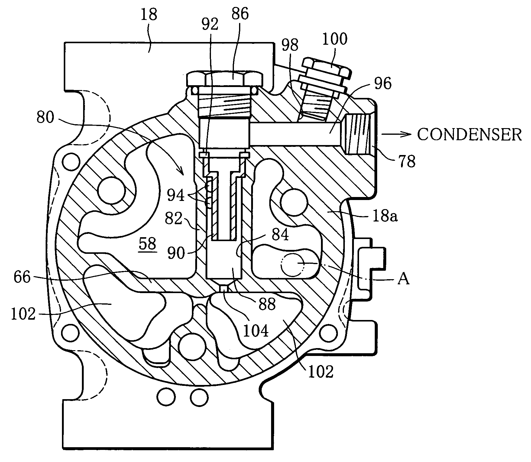
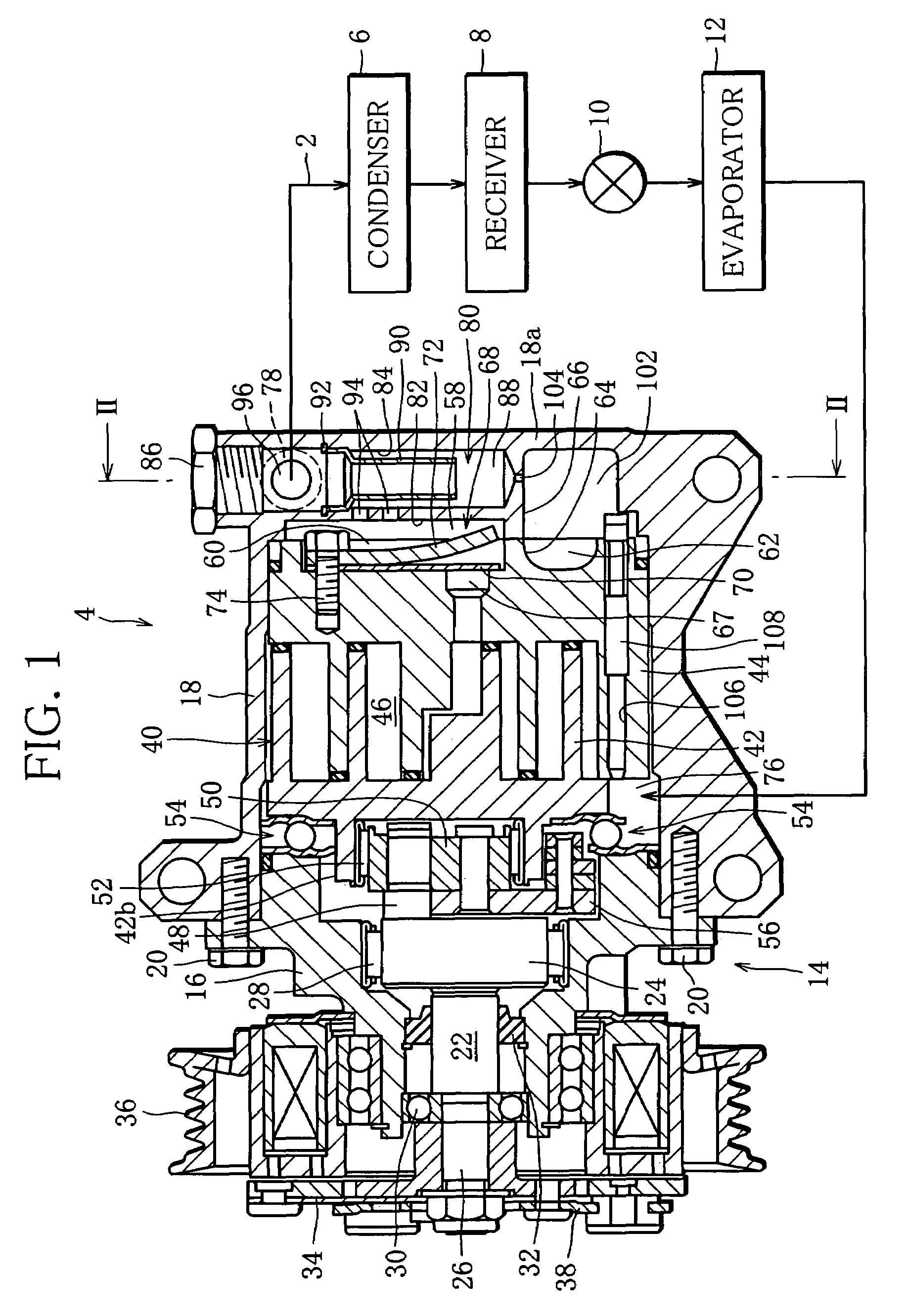
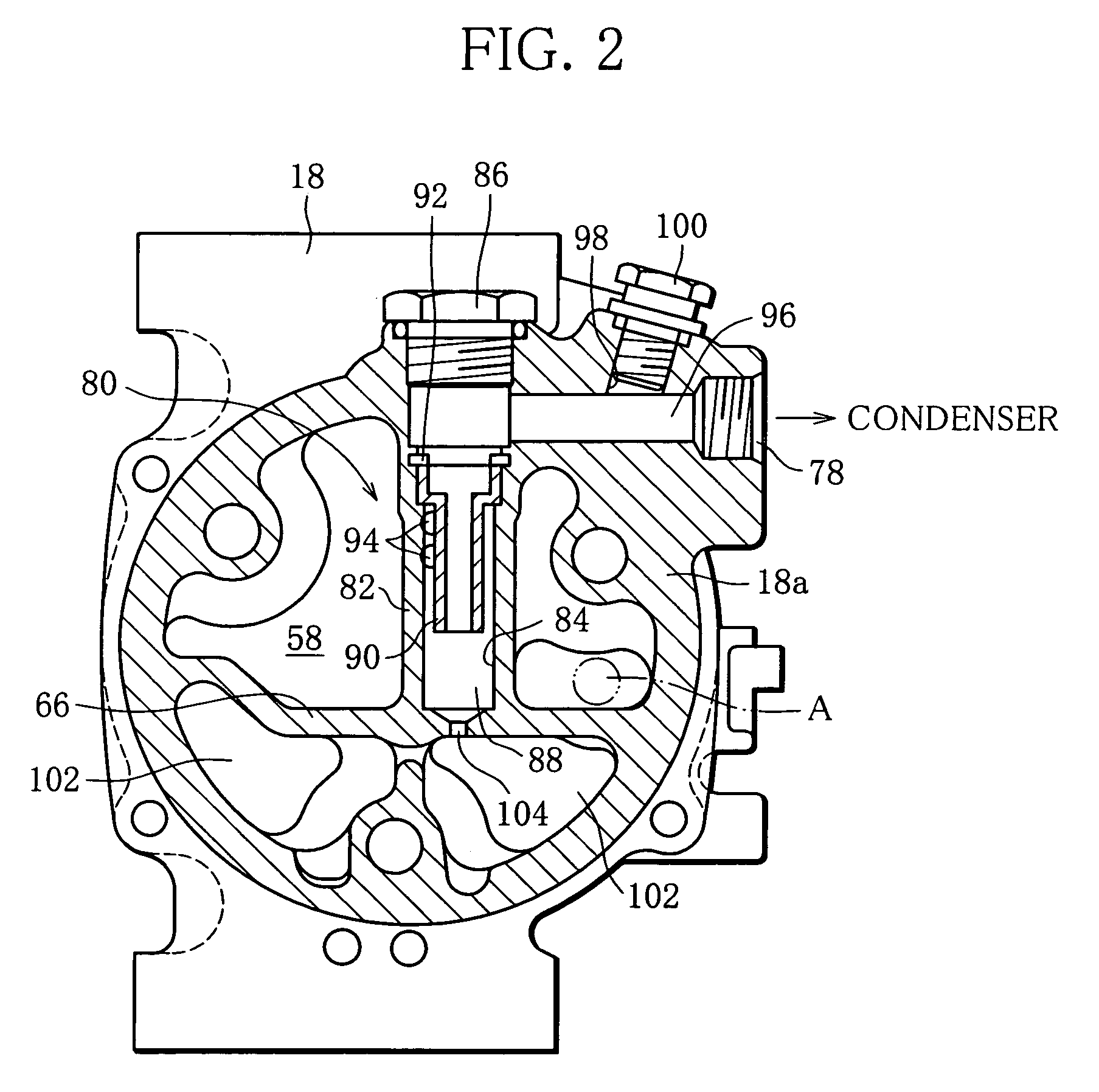
[0038]According to FIG. 1, a refrigerating circuit for an air conditioning system of a vehicle is provided with a refrigerant circulating path 2, and a compressor 4, a condenser 6, a receiver 8, an expansion valve 10 and an evaporator 12 are sequentially arranged in the circulating path 2. The compressor 4 compresses a refrigerant and discharges a high-pressure refrigerant toward the condenser 6. As a result, the refrigerant discharged from the compressor 4 circulates the path 2, and the refrigerating circuit attains refrigerating performance.

[0039]The refrigerant includes mist-like lubricating oil, and the lubricating oil in the refrigerant serves for not only lubricating bearings and various sliding surfaces in the compressor, but also sealing compression chambers of the compressor. These bearings, sliding surfaces and compression chambers will be mentioned later.

[0040]The compressor 4 in FIG. 1 is shown as a so-called scroll compressor. The compressor 4 is provided with a housing...


PUM


Abstract

A scroll compressor is provided with a housing having a discharge chamber to which a high-pressure refrigerant is discharged from a scroll unit, a discharge path connecting the discharge chamber and an outlet port 78 of the housing, a separating device arranged in the discharge path and separating a part of the lubricating oil from the refrigerant, and a relief valve arranged in a downstream side of the separating device in the discharge path. When a pressure within the discharge path exceeds a relief pressure, the relief valve is opened so as to eject the refrigerant to an outer side of the compressor from the discharging path.

Description

[0001]This Nonprovisional application claims priority under 35 U.S.C. 119(a) on Patent Application No. 2004-118225 filed in Japan on Apr. 13, 2004, the entire contents of which are hereby incorporated by reference.BACKGROUND OF THE INVENTION[0002]1. Field of the Invention[0003]The present invention relates to a compressor, and more particularly to a compressor arranged in a refrigerating circuit for an air conditioning system of a vehicle.[0004]2. Description of the Related Art[0005]This kind of compressor is used for compressing a refrigerant serving as a working fluid. In general, the refrigerant contains a mist-like lubricating oil, and the lubricating oil serves for not only lubricating sliding surfaces in the compressor, bearings and the like, but also sealing sliding surfaces in the compressor. However, in the case that the lubricating oil contained in the refrigerant is more, the lubricating oil causes to lower refrigerating performance of the refrigerating circuit.[0006]A co...

Claims


Application Information

Patent Timeline
Patent Type & Authority Patents(United States)
IPC IPC(8): F04C18/00F01C1/02F04C29/02F01C1/063F01C21/04F04C18/02F04C29/04
CPCF04C29/026F04C18/0215
Inventor ITO, KIYOFUMI
Owner SANDEN CORP
Why Eureka
Try Eureka