Endoscope with actively cooled illumination sources

a technology of illumination source and endoscope, which is applied in the field of medical devices, can solve the problems of limited column strength, limited flexibility, and inability to adjust the angle of the endoscope, and achieve the effects of low cost, easy assembly, and variation in stiffness

Active Publication Date: 2008-08-19
SCI MED LIFE SYST
View PDF674 Cites 146 Cited by
  • Summary
  • Abstract
  • Description
  • Claims
  • Application Information

AI Technical Summary

Benefits of technology

[0007]The single use endoscope of the present invention includes a flexible elongate tube or shaft and an illumination source that directs light onto a tissue sample. An image sensor and objective lens assembly at or adjacent the distal end of the endoscope captures reflected light to produce an image of the illuminated tissue. Images produced by the sensor are transmitted to a display device to be viewed by an examiner. In one embodiment, an imaging assembly at the distal end of the endoscope includes an inexpensive and easy to assemble set of components that house one or more light emitting diodes (LEDs), an image sensor such as a CMOS solid state image sensor and a lens assembly. The LEDs are thermally coupled to a heat exchanger, which may be air or liquid cooled in order to remove excess heat generated by the LEDs.
[0009]In one embodiment of the invention, the endoscope includes an articulation joint that is comprised of a number of low cost, easily assembled pieces that allow the distal end of the scope to be bent in a desired direction by the control cables. In one embodiment of the invention, the articulation joint exerts a restoring force such that upon release of a tensioning force, the distal end of the scope will straighten.
[0010]In another embodiment of the invention, the endoscope has a variation in stiffness along its length that allows the distal end to be relatively flexible while the more proximal regions of the scope have increased column strength and torque fidelity so that a physician can twist and advance the endoscope with greater ease and accuracy and with fewer false advances (“loops”). Variation in stiffness along the length can be provided by varying the durometer rating of materials that comprise a shaft of the endoscope. Operator-controlled, variable stiffness can be provided by the control cables that can be tightened or loosened to adjust the stiffness of the shaft. In yet another embodiment, the spacing between the components that comprise the articulation joint is selected to provide a variation in stiffness along the length of the articulation joint.

Problems solved by technology

By manipulating the control knobs, the examiner is usually able to steer the endoscope during insertion and direct it to a region of interest, in spite of the limitations of such traditional control systems, which are clumsy, non-intuitive, and friction-limited.
Common operator complaints about traditional endoscopes include their limited flexibility, limited column strength, and limited operator control of stiffness along the scope length.
Conventional endoscopes are expensive medical devices costing in the range of $25,000 for an endoscope, and much more for the associated operator console.
Conventional endoscopes are generally built of sturdy materials, which decreases the flexibility of the scope and thus can decrease patient comfort.
Furthermore, conventional endoscopes are complex and fragile instruments that frequently need expensive repair as a result of damage during use or during a disinfection procedure.

Method used


Image

  • Endoscope with actively cooled illumination sources
  • Endoscope with actively cooled illumination sources
  • Endoscope with actively cooled illumination sources

Examples


Embodiment Construction

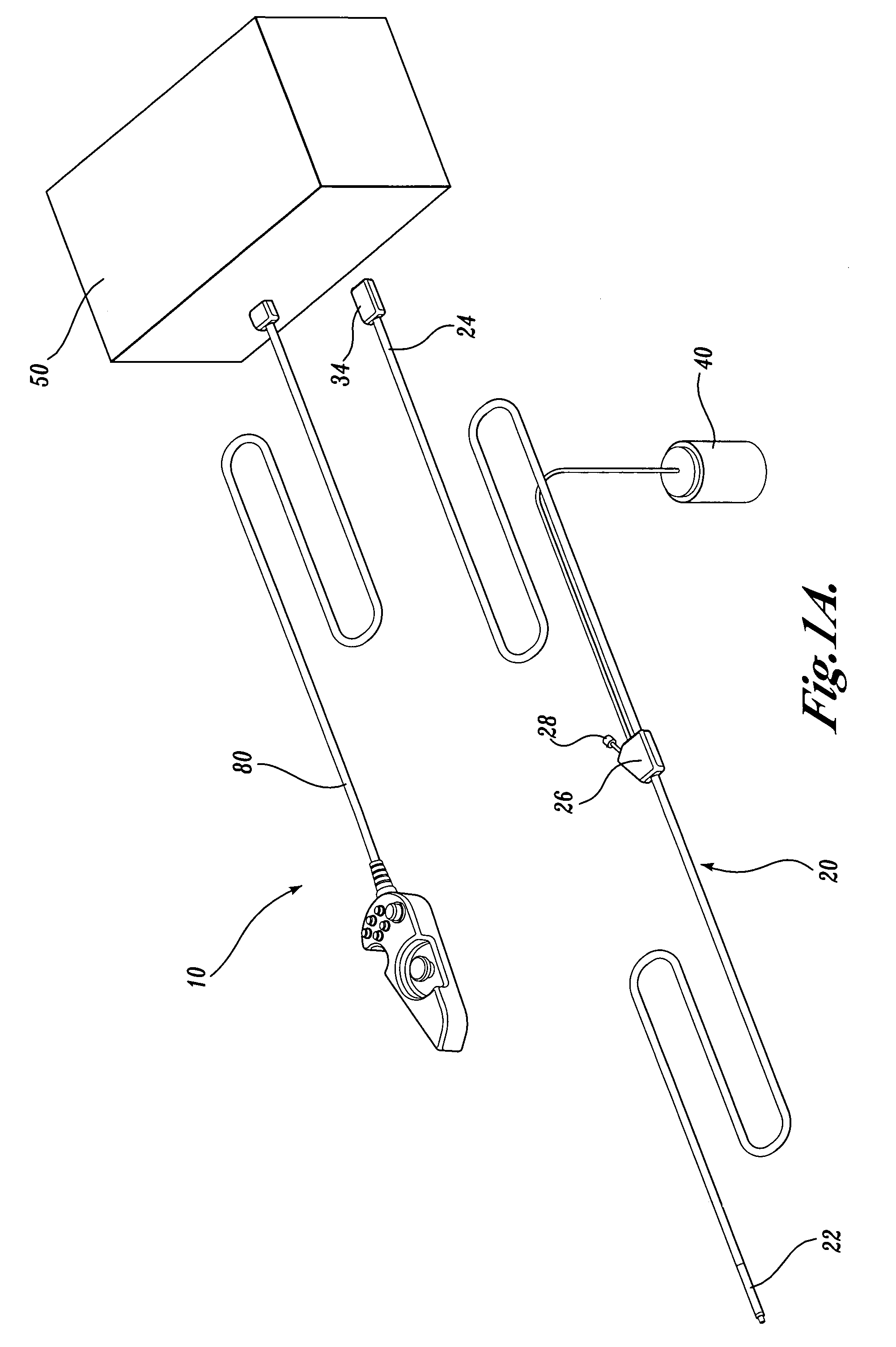
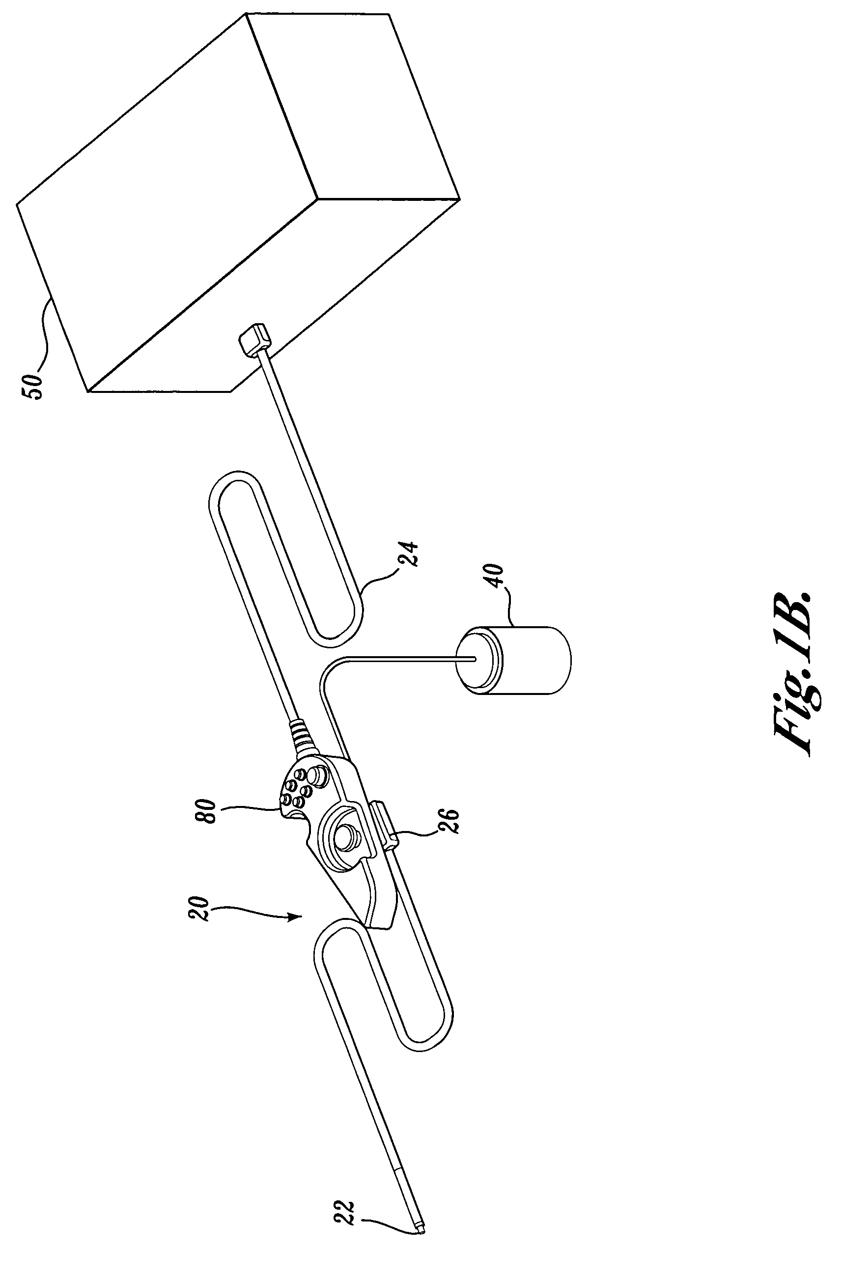
[0053]As indicated above, the present invention is an endoscopic video imaging system that allows a physician to view internal body cavities of a patient as well as to insert surgical instruments into the patient's body. An imaging endoscope used with the present invention is sufficiently inexpensive to manufacture such that the endoscope can be considered a single use, disposable item.

[0054]As shown in FIG. 1A, an endoscopic video imaging system 10 according to one embodiment of the present invention includes a single use imaging endoscope 20, a control cabinet 50 and a handheld controller 80. The single use endoscope 20 has a distal tip 22 that is advanced into a patient's body cavity and a proximal end 24 that is connected to the control cabinet 50. As will be explained in further detail below, the control cabinet 50 includes a number of actuators that control a steering mechanism within the endoscope 20 in order to change the orientation of the distal tip 22. A physician or thei...


PUM


Abstract

An endoscopic imaging system includes a reusable control cabinet having a number of actuators that control the orientation of a lightweight endoscope that is connectable thereto. The endoscope is used with a single patient and is then disposed. The endoscope includes an illumination mechanism, an image sensor, and an elongate shaft having one or more lumens located therein. An articulation joint at the distal end of the endoscope allows the distal end to be oriented by the actuators in the control cabinet. The endoscope is coated with a hydrophilic coating that reduces its coefficient of friction and because it is lightweight, requires less force to advance it to a desired location within a patient.

Description

CROSS-REFERENCE TO RELATED APPLICATION[0001]The present application is a continuation-in-part of U.S. patent application Ser. No. 10 / 406,149, filed Apr. 1, 2003, the benefit of which is claimed under 35 U.S.C. § 120 and is herein incorporated by reference.FIELD OF THE INVENTION[0002]The present invention relates to medical devices in general and therapeutic and diagnostic endoscopes in particular.BACKGROUND OF THE INVENTION[0003]As an aid to the early detection of disease, it has become well established that there are major public health benefits from regular endoscopic examinations of internal structures such as the alimentary canals and airways, e.g., the esophagus, lungs, colon, uterus, and other organ systems. A conventional imaging endoscope used for such procedures comprises a flexible tube with a fiber optic light guide that directs illuminating light from an external light source to the distal tip where it exits the endoscope and illuminates the tissue to be examined. Freque...

Claims


Application Information

Patent Timeline
Patent Type & Authority Patents(United States)
IPC IPC(8): A61B1/00A61B1/04A61B1/06A61B1/005A61B1/015A61B1/05A61B1/31
CPCA61B1/00071A61B1/04A61B1/00147A61B1/0051A61B1/0052A61B1/0055A61B1/0057A61B1/0016A61B1/008A61B1/0008A61B1/015A61B1/05A61B1/0676A61B1/0684A61B1/31A61B1/0638A61B2017/00309A61B2017/00314A61B2017/00327A61B2017/0042A61B1/00042A61B2090/309A61B2090/306A61B1/00096
Inventor BANIK, MICHAEL S.COUVILLON, JR., LUCIEN ALFREDBOULAIS, DENNIS R.FANTONE, STEPHEN D.ORBAND, DANIEL G.SABER, MICHAEL P.BRAUNSTEIN, DANIEL J.
Owner SCI MED LIFE SYST
Why Eureka
Try Eureka