
System and method for beamforming using a microphone array

a beamforming system and microphone array technology, applied in direction finders using ultrasonic/sonic/infrasonic waves, special services for subscribers, instruments, etc., can solve the problems of only providing near-optimal noise suppression for off-beam sounds, beamforming techniques designed for one particular microphone array may not provide acceptable, and the shape of beams cannot adapt to the changes of surrounding environment, etc., to achieve optimal beam width, maximum noise suppression, and easy adaptability

Inactive Publication Date: 2008-08-19
MICROSOFT TECH LICENSING LLC
View PDF4 Cites 116 Cited by
  • Summary
  • Abstract
  • Description
  • Claims
  • Application Information

AI Technical Summary

Benefits of technology

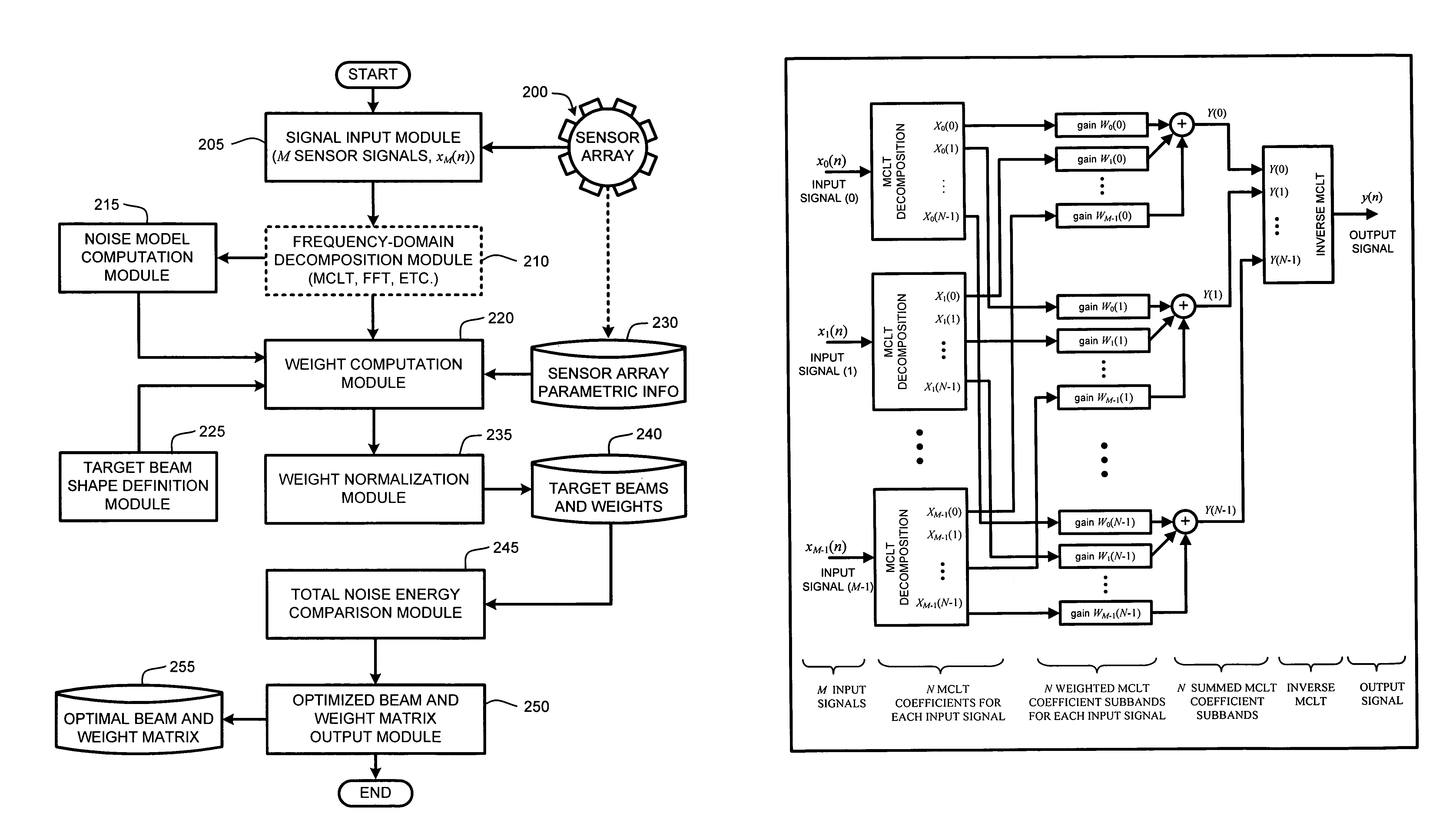
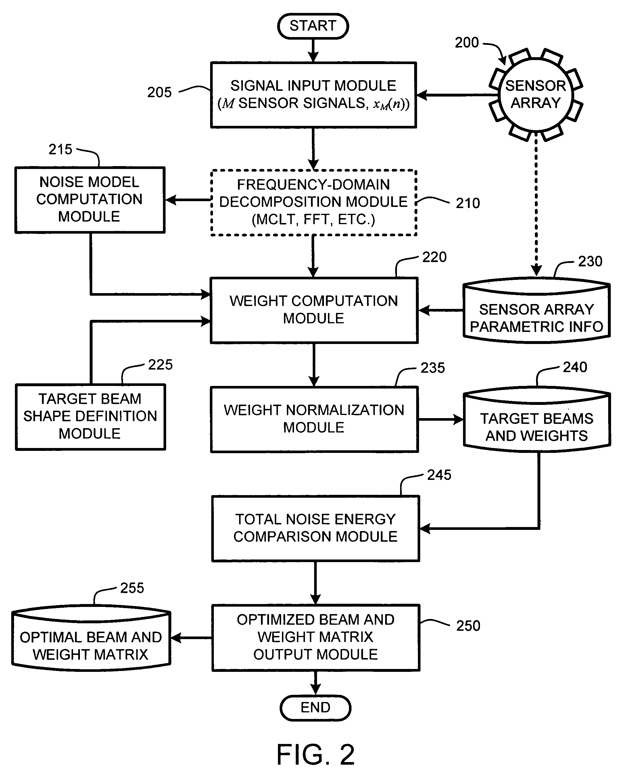
[0017]The weights computed for the weight matrix are determined by calculating frequency-domain weights for a desired “focus points” distributed throughout the workspace around the microphone array. The weights in this weight matrix are optimized so that beams designed by the generic beamformer will provide maximal noise suppression (based on the computed noise models) under the constraints of unit gain and zero phase shift in any particular focus point for each frequency band. These constraints are applied for an angular area around the focus point, called the “focus width.” This process is repeated for each frequency band of interest, thereby resulting in optimal beam widths that vary as a function of frequency for any given focus point.
[0018]In one embodiment, beamforming processing is performed using a frequency-domain technique referred to as Modulated Complex Lapped Transforms (MCLT). However, while the concepts described herein use MCLT domain processing by way of example, it should be appreciated by those skilled in the art, that these concepts are easily adaptable to other frequency-domain decompositions, such as, for example, fast Fourier transform (FFT) or FFT-based filter banks. Note that because the weights are computed for frequency domain weighting, the weight matrix is an N×M matrix, where N is the number of MCLT frequency bands (i.e., MCLT subbands) in each audio frame and M is the number of microphones in the array. Therefore, assuming, for example, the use of 320 frequency bins for MCLT computations, an optimal beam width for any particular focus point can be described by plotting gain as a function of incidence angle and frequency for each of the 320 MCLT frequency coefficients. Note that using a large number of MCLT subbands (e.g. 320) allows for two important advantages of the frequency-domain technique: i) fine tuning of the beam shapes for each frequency subband; and ii) simplifying the filter coefficients for each subband to single complex-valued gain factors, allowing for computationally efficient implementations.
[0022]In general, in finding the optimal solution for the weight matrix, two contradicting effects are balanced. Specifically, given a narrow focus area for the beam shape, ambient noise energy will naturally decrease due to increased directivity. In addition, non-correlated noise (including electrical circuit noise) will naturally increase since a solution for better directivity will consider smaller and smaller phase differences between the output signals from the microphones, thereby boosting the non-correlated noise. Conversely, when the target focus area of the beam shape is larger, there will naturally be more ambient noise energy, but less non-correlated noise energy.
[0026]The purpose of providing the target weight functions is to minimize the effects of signals originating from points outside the main beam on beamformer computations. Therefore, in a tested embodiment, target points inside the target beam were assigned a gain of 1.0 (unit gain); target points within the transition area were assigned a gain of 0.1 to minimize the effect of such points on beamforming computations while still considering their effect; finally points outside of the transition area of the target beam were assigned a gain of 2.0 so as to more fully consider and strongly reduce the amplitudes of sidelobes on the final designed beams. Note that using too high of a gain for target points outside of the transition area can have the effect of overwhelming the effect of target points within the target beam, thereby resulting in less than optimal beamforming computations.

Problems solved by technology

Unfortunately, as a result of the high complexity, and thus large computational overhead, of such approaches, more emphasis has been given to finding near-optimal solutions, rather than optimal solutions.
In general, with fixed-beam formation, the beam shapes do not adapt to changes in the surrounding noises and sound source positions.
Further, the near-optimal solutions offered by such approaches tend to provide only near-optimal noise suppression for off-beam sounds or noise.
Consequently, a beamforming technique designed for one particular microphone array may not provide acceptable results when applied to another microphone array of a different geometry.
Unfortunately, one disadvantage of such techniques is their significant computational requirements and slow adaptation, which makes them less robust to wide varieties in application scenarios.
However, given the relatively high dimensionality of the weight matrix (2M real numbers per frequency band, for a total of N×2M numbers), which can be considered as a multimodal hypersurface, and because the functions are nonlinear, finding the optimal weights as points in the multimodal hypersurface is very computationally expensive, as it typically requires multiple checks for local minima.
Specifically, given a narrow focus area for the beam shape, ambient noise energy will naturally decrease due to increased directivity.
However, abrupt functions such as rectangular functions can cause ripples in the beam shape.
Note that using too high of a gain for target points outside of the transition area can have the effect of overwhelming the effect of target points within the target beam, thereby resulting in less than optimal beamforming computations.
However, this set of weights does not necessarily meet the aforementioned constraints of unit gain and zero phase shift in the focus point for each work frequency band.
At this point, the generic beamformer has not yet considered an overall minimization of the total noise energy as a function of beam width.
Frequency ranges with particularly high noise energy levels are then weighted more heavily to increase their effect on the overall beamforming computations, thereby resulting in a greater attenuation of noise within such frequency ranges.
However, it should be clear that noise levels and sources often change as a function of time.

Method used


Image

  • System and method for beamforming using a microphone array
  • System and method for beamforming using a microphone array
  • System and method for beamforming using a microphone array

Examples


Embodiment Construction

[0040]In the following description of the preferred embodiments of the present invention, reference is made to the accompanying drawings, which form a part hereof, and in which is shown by way of illustration specific embodiments in which the invention may be practiced. It is understood that other embodiments may be utilized and structural changes may be made without departing from the scope of the present invention.

1.0 Exemplary Operating Environment:

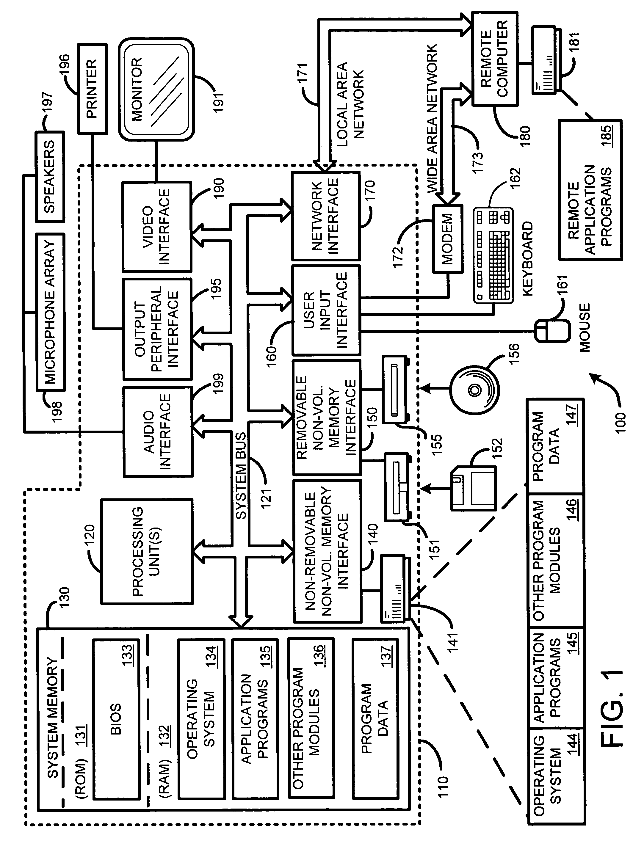
[0041]FIG. 1 illustrates an example of a suitable computing system environment 100 with which the invention may be implemented. The computing system environment 100 is only one example of a suitable computing environment and is not intended to suggest any limitation as to the scope of use or functionality of the invention. Neither should the computing environment 100 be interpreted as having any dependency or requirement relating to any one or combination of components illustrated in the exemplary operating environment 100.

[0042]The in...


PUM


Abstract

The ability to combine multiple audio signals captured from the microphones in a microphone array is frequently used in beamforming systems. Typically, beamforming involves processing the output audio signals of the microphone array in such a way as to make the microphone array act as a highly directional microphone. In other words, beamforming provides a “listening beam” which points to a particular sound source while often filtering out other sounds. A “generic beamformer,” as described herein automatically designs a set of beams (i.e., beamforming) that cover a desired angular space range within a prescribed search area. Beam design is a function of microphone geometry and operational characteristics, and also of noise models of the environment around the microphone array. One advantage of the generic beamformer is that it is applicable to any microphone array geometry and microphone type.

Description

BACKGROUND[0001]1. Technical Field[0002]The invention is related to finding the direction to a sound source in a prescribed search area using a beamsteering approach with a microphone array, and in particular, to a system and method that provides automatic beamforming design for any microphone array geometry and for any type of microphone.[0003]2. Background Art[0004]Localization of a sound source or direction within a prescribed region is an important element of many systems. For example, a number of conventional audio conferencing applications use microphone arrays with conventional sound source localization (SSL) to enable speech or sound originating from a particular point or direction to be effectively isolated and processed as desired.[0005]For example, conventional microphone arrays typically include an arrangement of microphones in some predetermined layout. These microphones are generally used to simultaneously capture sound waves from various directions and originating fro...

Claims


Application Information

Patent Timeline
Patent Type & Authority Patents(United States)
IPC IPC(8): H04R3/00G01S3/80G06F15/00G10L19/14G10L21/00H04B15/00H04B3/00H04R1/40G01S5/18G10K11/00G10K11/178G10L11/00H04M3/56H04R1/32H04R5/027
CPCH04R3/005B42D7/00G09B29/006
Inventor TASHEV, IVANMALVAR, HENRIQUE
Owner MICROSOFT TECH LICENSING LLC
Learn More