
Noise suppression circuit for a wireless device

a wireless device and noise suppression technology, applied in the field of voice coding, can solve the problems of incoherent noise signals of current products, performance degradation of ambient noise, and serious obstacles to the development of acceptable solutions of ambient noise, and achieve the effect of suppressing incoherent noise signals

Inactive Publication Date: 2007-02-06
MALIKIE INNOVATIONS LTD
View PDF18 Cites 17 Cited by
  • Summary
  • Abstract
  • Description
  • Claims
  • Application Information

AI Technical Summary

Benefits of technology

[0009]The present invention provides many advantages over presently known systems and methods, such as: (1) the achievement of noise suppression while preserving speech components in the 100–600 Hz frequency band; (2) the exploitation of time and frequency differences between the speech and noise sources to produce noise suppression; (3) only two microphones are used to achieve effective noise suppression and these may be placed in an arbitrary geometry; (4) the microphones require no calibration procedures; (5) enhanced performance in diffuse noise environments since it uses a speech component; (6) a normalized coherence estimator that offers improved accuracy over shorter observation periods; (7) makes the inverse filter length dependent on the local signal-to-noise ratio (SNR); (8) ensures spectral continuity by post filtering and feedback; (9) the resulting reconstructed signal contains significant noise suppression without loss of intelligibility or fidelity where for vocoders and voice recognition programs the recovered signal is easier to process. These are just some of the many advantages of the invention, which will become apparent to one of ordinary skill upon reading the description of the preferred embodiment, set forth below.

Problems solved by technology

Unfortunately, current products do not perform equally well in many of these environments, and a major source of performance degradation is ambient noise.
Further, for safe operation, many of these hand-held products need to offer hands-free operation, and here in particular, ambient noise possess a serious obstacle to the development of acceptable solutions.
The conversion from analog speech to a compressed digital data stream is, however, very error prone when the input signal contains moderate to high ambient noise levels.
The characteristics of ambient noise are poorly captured by these models.
Thus, when ambient noise is present, the parameters estimated by the vocoder algorithm may contain significant errors and the reconstructed signal often sounds unlike the original.
Like vocoders, most voice recognition methods rely on parametric models of speech and human conversation and do not take into account the effect of ambient noise.

Method used


Image

  • Noise suppression circuit for a wireless device
  • Noise suppression circuit for a wireless device
  • Noise suppression circuit for a wireless device

Examples


Embodiment Construction

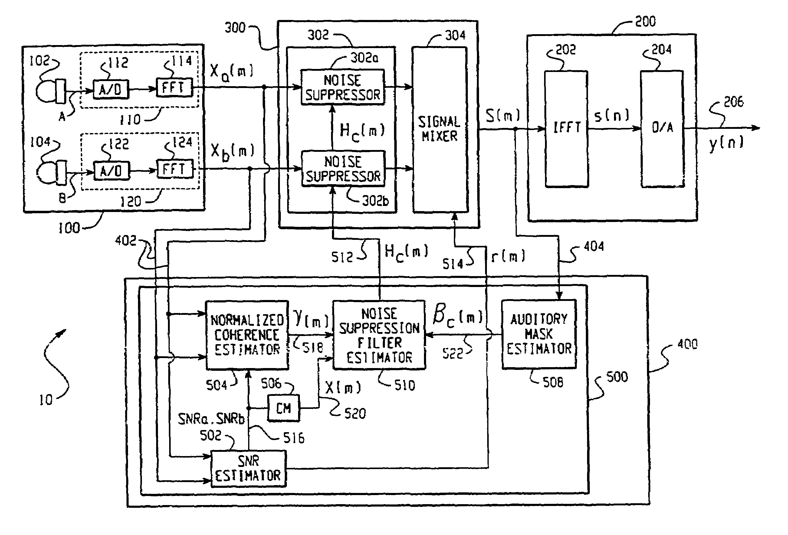
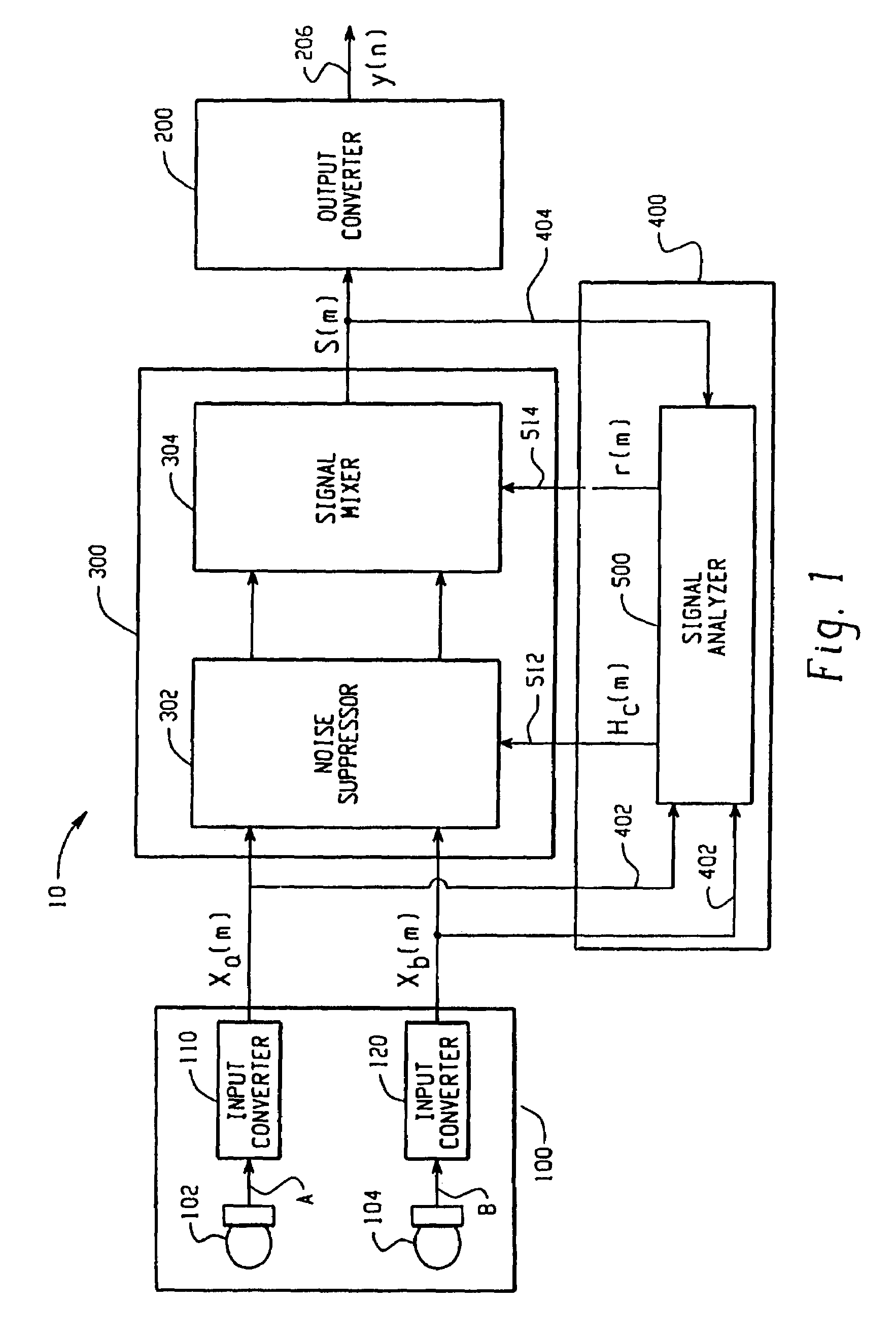
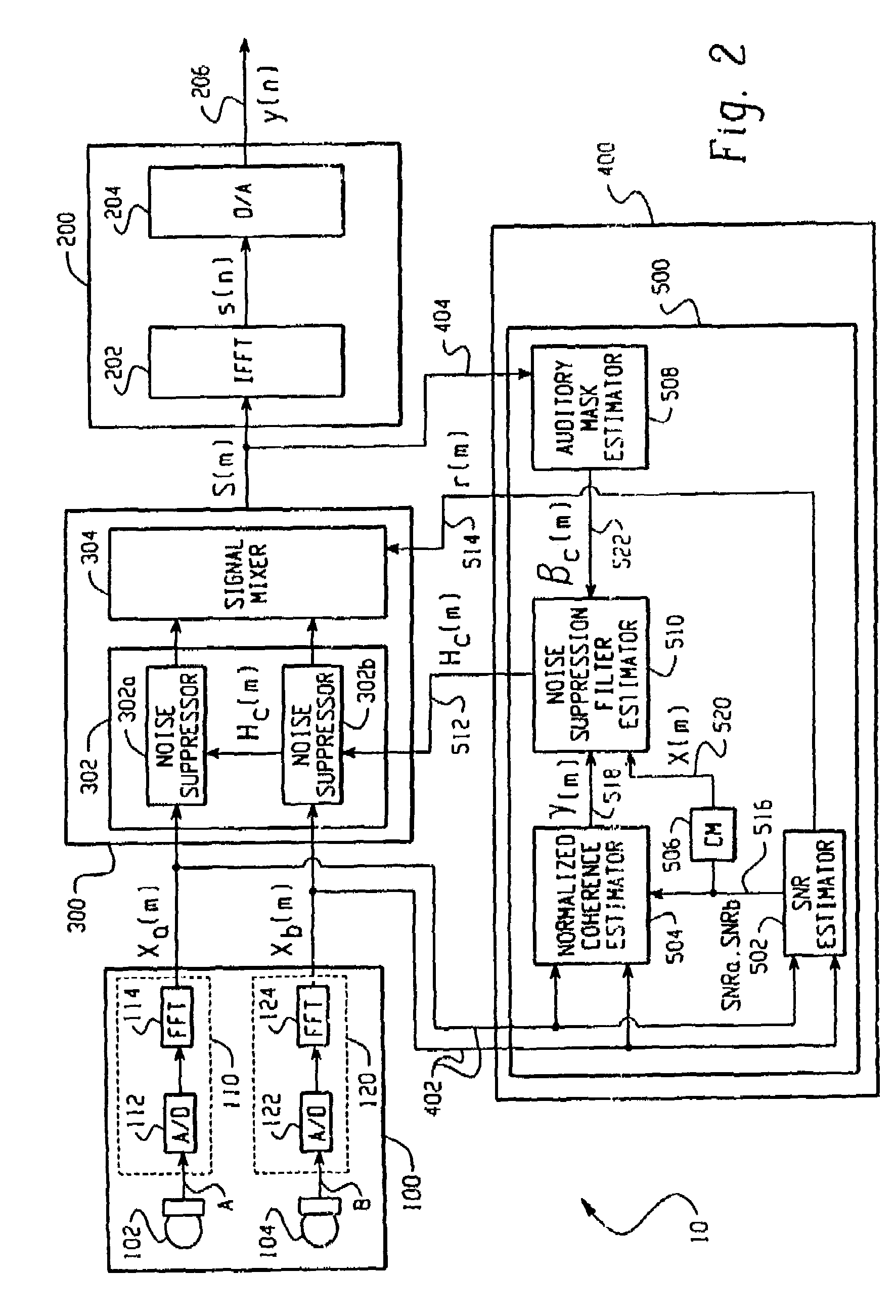
[0013]Turning now to the drawing figures, FIG. 1 sets forth a preferred embodiment of an adaptive noise suppression system (ANSS) 10 according to the present invention. The data flow through the ANSS 10 flows through an input converting stage 100 and an output converting stage 200. Between the input stage 100 and the output stage 200 is a filtering stage 300 and an analyzing stage 400. The analyzing stage 400 includes a feed-forward path 402 and a feedback path 404.

[0014]Analog signals A(n) and B(n) are first received in the input stage 100 at receivers 102 and 104, which are preferably microphones. These analog signals A and B are then converted to digital signals Xn(m) (n=a,b) in input converters 110 and 120. After this conversion, the digital signals Xn(m) are fed to the filtering stage 300 and the feed-forward path 402 of the analyzing stage 400. The filtering stage 300 also receives control signals Hc(m) and r(m) from the analyzing stage 400, which are used to process the digit...


PUM


Abstract

An adaptive noise suppression system includes an input A / D converter, an analyzer, a filter, and a output D / A converter. The analyzer includes both feed-forward and feedback signal paths that allow it to compute a filtering coefficient, which is input to the filter. In these paths, feed-forward signal are processed by a signal to noise ratio estimator, a normalized coherence estimator, and a coherence mask. Also, feedback signals are processed by a auditory mask estimator. These two signal paths are coupled together via a noise suppression filter estimator. A method according to the present invention includes active signal processing to preserve speech-like signals and suppress incoherent noise signals. After a signal is processed in the feed-forward and feedback paths, the noise suppression filter estimator then outputs a filtering coefficient signal to the filter for filtering the noise out of the speech and noise digital signal.

Description

CROSS-REFERENCE TO RELATED APPLICATIONS[0001]This application is a continuation of U.S. application Ser. No. 10 / 223,409, filed on Aug. 19, 2002 now U.S. Pat. No. 6,647,367, and entitled “Noise Suppression Circuit,” which is a continuation of U.S. application Ser. No. 09 / 452,623, now U.S. Pat. No. 6,473,733, filed on Dec. 1, 1999. The entire specification of these applications, including the drawing figures, are hereby incorporated into the present application by reference.BACKGROUND OF THE INVENTION[0002]1. Field of the Invention[0003]The present invention is in the field of voice coding. More specifically, the invention relates to a system and method for signal enhancement in voice coding that uses active signal processing to preserve speech-like signals and suppresses incoherent noise signals.[0004]2. Description of the Related Art[0005]The emergence of wireless telephony and data terminal products has enabled users to communicate with anyone from almost anywhere. Unfortunately, c...

Claims


Application Information

Patent Timeline
Patent Type & Authority Patents(United States)
IPC IPC(8): G10L19/14G10L21/02
CPCG10L21/0208G10L2021/02166G10L2021/02165
Inventor MCARTHUR, DEANREILLY, JIM
Owner MALIKIE INNOVATIONS LTD
Learn More